Stator design for permanent magnet motor with combination slot wedge and tooth locator

a permanent magnet motor and locator technology, applied in the direction of synchronous motors, dynamo-electric machines, magnetic circuit shapes/forms/construction, etc., can solve the problems of low power density, noise, power loss and inaccuracy, and difficulty in insertion of stator windings, so as to achieve low cogging torque and high power density

a permanent magnet motor and locator technology, applied in the direction of synchronous motors, dynamo-electric machines, magnetic circuit shapes/forms/construction, etc., can solve the problems of low power density, noise, power loss and inaccuracy, and difficulty in insertion of stator windings, so as to achieve low cogging torque and high power density

US6844653B2Inactive Publication Date: 2005-01-18VALEO ELECTRICAL SYST

Image

  • Stator design for permanent magnet motor with combination slot wedge and tooth locator
  • Stator design for permanent magnet motor with combination slot wedge and tooth locator
  • Stator design for permanent magnet motor with combination slot wedge and tooth locator

Examples


Embodiment Construction

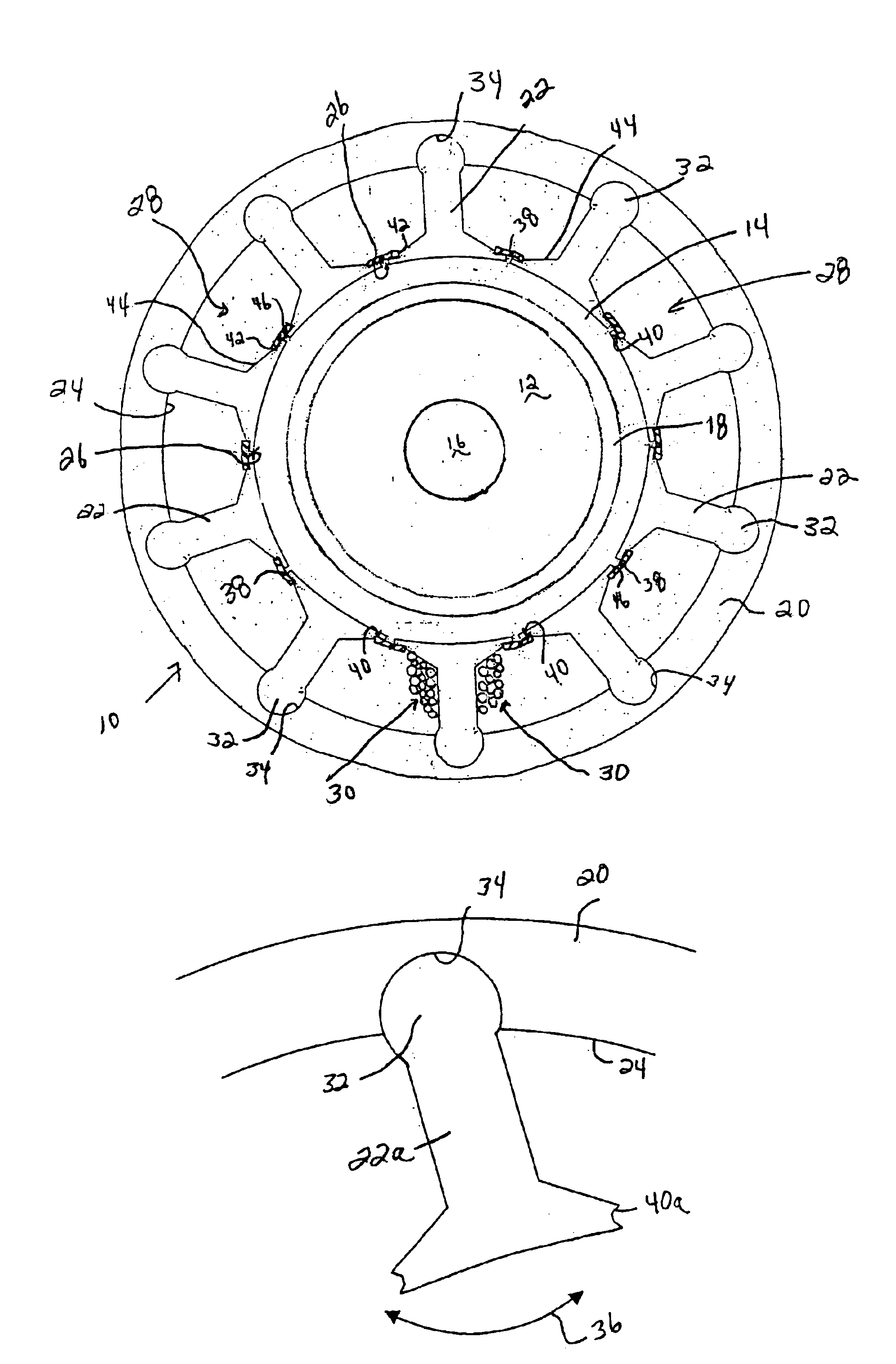
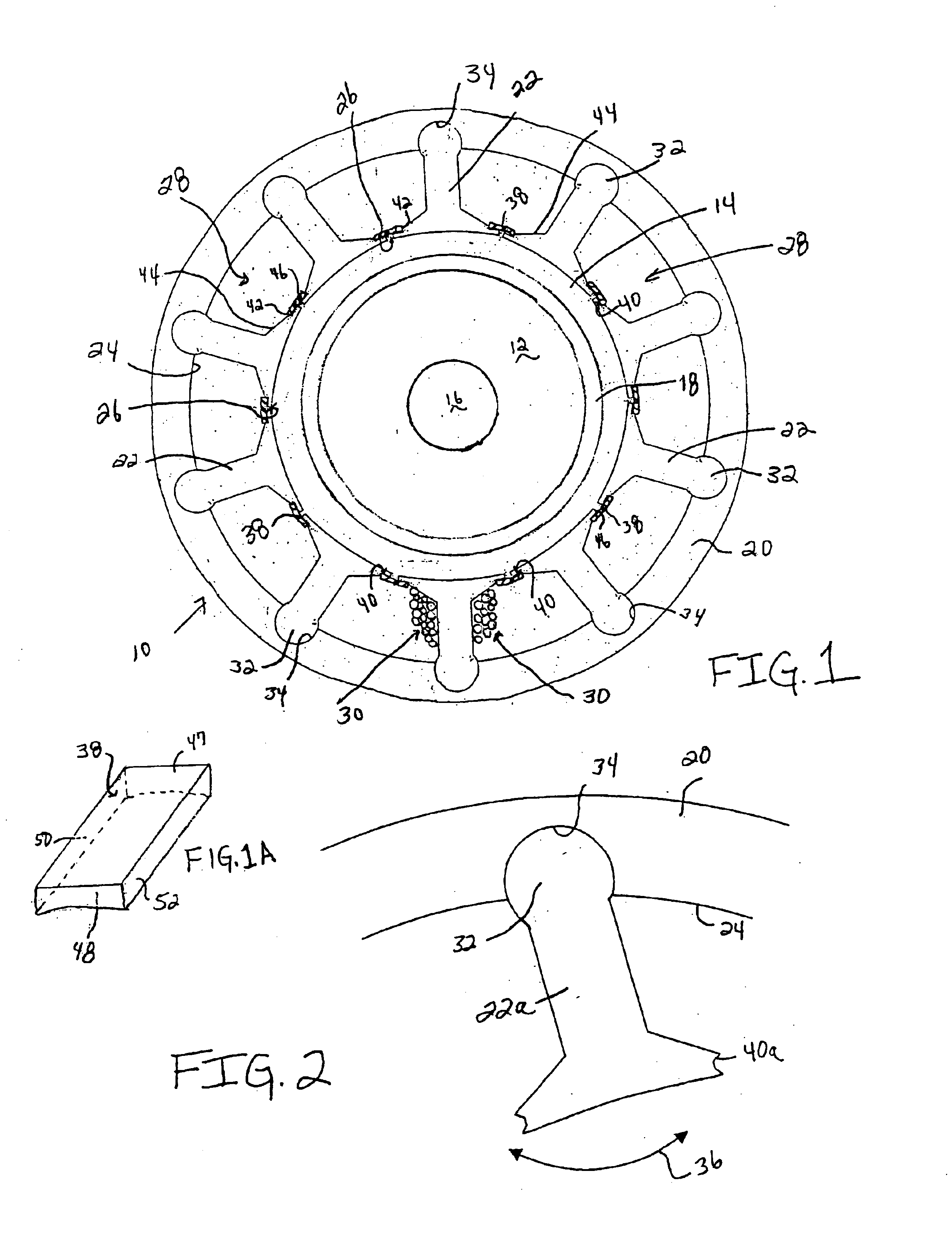
The drawing, particularly FIGS. 1-11, show the stator design for a permanent magnet motor according to the present invention. Although all of the drawing figures show the stator design incorporated into the common configuration where the rotor rotates on a shaft, and the stator surrounds the rotor, the invention can be used with a so-called “inside-out” design, that is, where the rotor rotates around the stator. FIG. 1 shows one design for a segmented stator 10 surrounding a rotor 12 and separated by an air gap 14. The rotor 12 is mounted on a rotatable shaft 16 and is constructed according to any number of known designs, such as a rotor comprising a rotor yoke with discrete permanent magnets or with a permanent magnet ring. In FIG. 1, a permanent magnet ring 18 forms a plurality of poles about the rotor 12.

Segmented stators are known whereby the stator comprises a plurality of stator segment assemblies separately wound with conductors before assembly in a motor. Such stator assembl...


PUM


Abstract

A segmented stator for a permanent magnet motor. The stator includes a plurality of stator segments forming an annular stator yoke and a plurality of stator teeth extending from an edge of the stator yoke. At least one coupling is between adjacent stator segments and shaped to allow movement of adjacent teeth in a so-called loose tooth design. Slot wedges are located between adjacent teeth to prevent the conductive windings from moving out of the slots through the slot openings. The slot wedges also prevent movement of adjacent teeth with respect to one another. The segmented stator can comprise an annular yoke with a plurality of discrete teeth or a plurality of assemblies including a rim section and a tooth section. The slot wedges can be keyed wedges that maintain their position through interlocking and / or can be integrated with a stator bobbin.

Description

BACKGROUND OF THE INVENTION1. Field of the InventionThe invention relates in general to a stator for permanent magnet motors, and particularly to a stator design for a brushless permanent magnet motor that includes a combination slot wedge and tooth locator.2. Description of the Related ArtPermanent magnet motors include a stator core, which is typically made of a stack of thin, metal laminations. The laminations are usually round, with a central opening. The stator core thus is generally cylindrical in shape, with a cavity extending longitudinally about the central axis of the core. In brushless permanent magnet motors, each stator lamination includes radially-extending openings from the central opening, generally called slots or notches, that are aligned when stacked to receive stator windings, or conductors, wound around the “teeth” formed by the radially-extending openings. The stator core surrounds a rotor, typically consisting of a circular steel shaft or a stack of annular la...

Claims


Application Information

Patent Timeline
18 Jan 2005
Publication
US6844653B2
IPC
H02K3/48; H02K3/34; H02K1/14; H02K3/32
CPC
H02K1/148; H02K3/48; H02K3/345
Inventors
KOLOMEITSEV, SERGEI F.; SURIANO, JOHN R.