Electric motor with minimized cogging and related method of determining stator pole geometry

a technology of electric motors and cogging, applied in the direction of dynamo-electric machines, magnetic circuit shapes/forms/construction, supports/enclosements/casings, etc., can solve the problems of reducing output torque, the effect of completely minimizing cogging torque, and reducing manufacturing costs, so as to reduce manufacturing costs and design labor hours. , the effect of easy efficient steps

Inactive Publication Date: 2009-08-18
DENSO CORP
View PDF20 Cites 2 Cited by
  • Summary
  • Abstract
  • Description
  • Claims
  • Application Information

AI Technical Summary

Benefits of technology

[0008]The present invention has been completed with the above issues in mind and has an object to provide an electric motor, which includes a rotor and a stator having a stator pole geometry to provide an equalized magnetic body distribution pattern over a circumferential periphery of the stator, and a method of determining a stator pole geometry for minimizing cogging torque in the electric motor.
[0009]To achieve the above object, one aspect of the present invention provides an electric motor comprising a stator having a circumferential periphery on which a plurality of stator poles are disposed and a rotor rotatable in face-to-face relationship with the stator and having an outer periphery facing the circumferential periphery of the stator. The stator includes magnetic reluctance equalizing means associated with the stator poles, respectively, to minimize a difference in magnetic reluctance along the circumferential periphery of the stator.
[0010]With such a structure mentioned above, the stator poles have the magnetic reluctance equalizing elements, respectively, by which the electric motor can be manufactured in a simplified construction with minimized cogging torque. Also, the electric motor can be manufactured with a minimum number component parts at low costs.

Problems solved by technology

However, with the skew angle set at too large a value, a drop occurs in utilization efficiency of a magnetic flux of the rotor, resulting in a decrease in output torque.
In such a case, cogging torque cannot be completely removed.
By the way, with the related art technique of employing added notches as disclosed in the above literature, magnetic reluctances occurring in the air gap segments between the stator cores and the added notches unequally vary with the resultant occurrence of issues wherein the added notches are effective to reduce cogging torque to some extent but have no remarkable effect of completely minimizing cogging torque.

Method used


Image

  • Electric motor with minimized cogging and related method of determining stator pole geometry
  • Electric motor with minimized cogging and related method of determining stator pole geometry
  • Electric motor with minimized cogging and related method of determining stator pole geometry

Examples


first embodiment

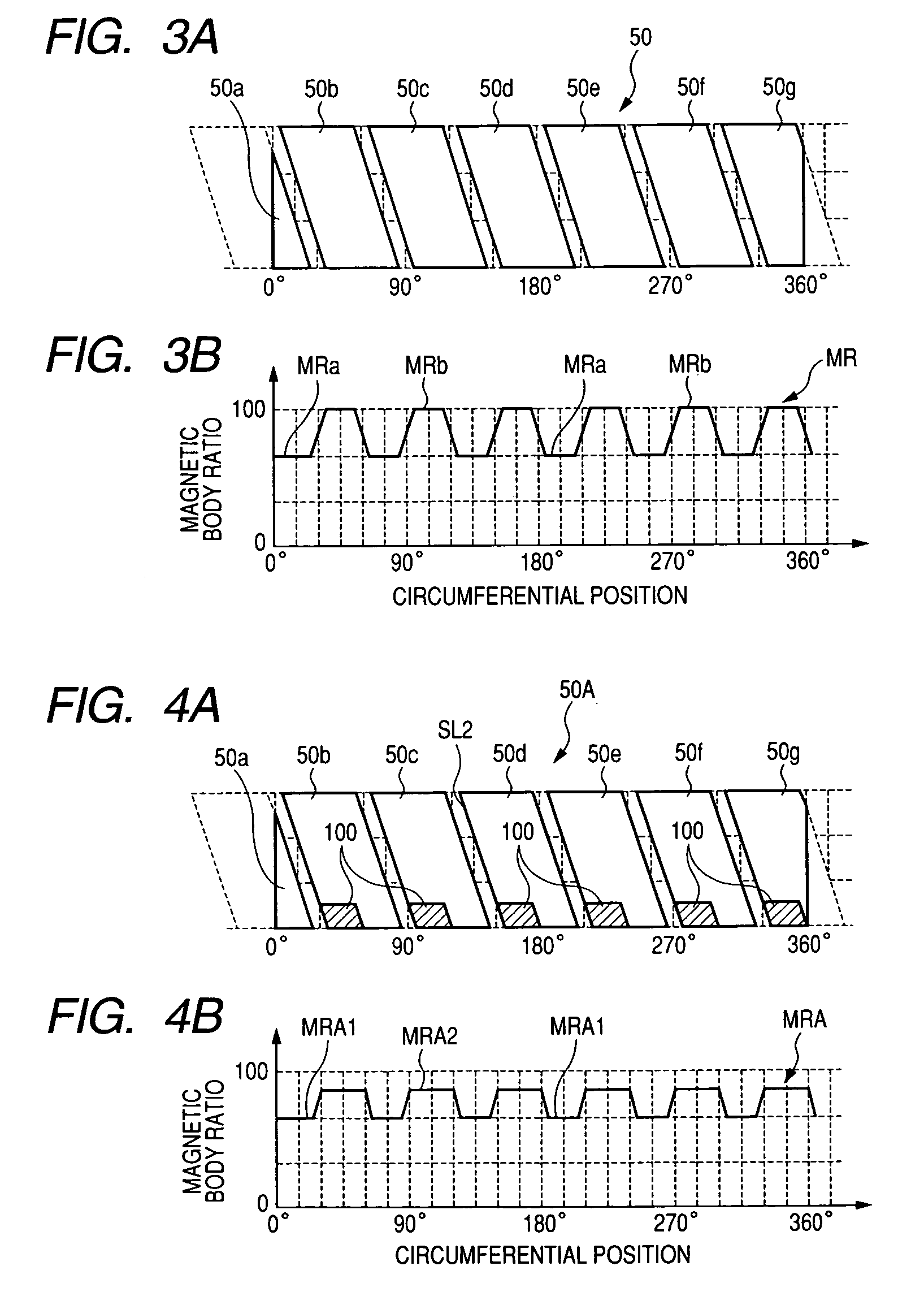
[0098]FIGS. 4A and 4B are views showing an electric motor of a first embodiment according to the present invention. With the electric motor of the present embodiment, a stator 50A fundamentally has the same structure as the stator 50 shown in FIG. 3A except for stator poles 50b to 50g having one axial ends provided with magnetic reluctance equalizing elements including non-magnetic body segments 100, respectively, in a high-ratio magnetic body distribution area. With the stator 50A having the high-ratio magnetic body distribution area additionally incorporating the non-magnetic body segments 100 as shown in FIG. 4A, the stator 50A has low-ratio magnetic body distribution areas MRA1 and high-ratio magnetic body distribution areas MRA2 that vary in a minimized range MRA along the circumferential periphery of the stator 50A. Since the low-ratio magnetic body distribution areas MRA1 and the high-ratio magnetic body distribution areas MRA2 have less variation in the magnetic body distrib...

second embodiment

[0099]FIGS. 5A and 5B are views showing an electric motor of a second embodiment according to the present invention. With the electric motor of the present embodiment, a stator 50B fundamentally has the same structure as the stator 50 shown in FIG. 3A except for stator poles 50b to 50g having one axial ends provided with magnetic reluctance equalizing elements including magnetic body segments 110, respectively, in an area laying at a low-ratio magnetic body distribution area. With the stator 50B having the low-ratio magnetic body distribution area additionally incorporating the magnetic body segments 110 as the magnetic reluctance equalizing elements as shown in FIG. 5A, the stator 50B has low-ratio magnetic body distribution areas MRB1 and high-ratio magnetic body distribution areas MRB2 that vary in a minimized range along the circumferential periphery of the stator 50B. Since the low-ratio magnetic body distribution areas MRB1 and the high-ratio magnetic body distribution areas M...

third embodiment

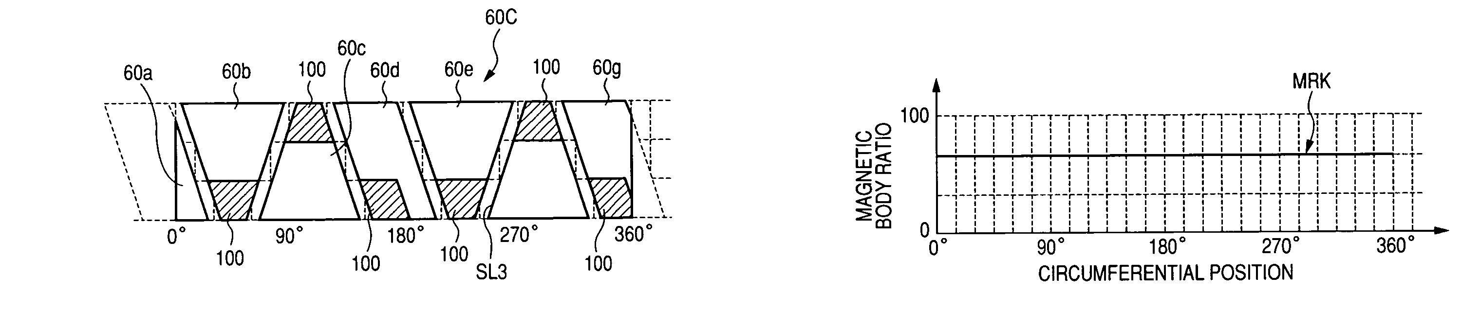
[0102]FIGS. 7A and 7B are views showing an electric motor of a third embodiment according to the present invention. With the electric motor of the present embodiment, a stator 60A fundamentally has the same structure as the stator 60 shown in FIG. 6A except for stator poles 60b to 60g having axial ends provided with magnetic reluctance equalizing elements including non-magnetic body segments 100, respectively, that are alternately disposed in opposing axial ends of the stator poles 60b to 60g in a high-ratio magnetic body distribution area. In particular, with the structure shown in FIG. 7A, the trapezoid-shaped stator magnet poles 60b, 60c, 60e, 60f have narrow ends incorporating the non-magnetic body segments 100, respectively. The stator poles 60d, 60g also incorporate the non-magnetic body segments 100, respectively. With such a stator 60A having the high-ratio magnetic body distribution areas additionally incorporating the non-magnetic body segments 100 as shown in FIG. 7A, the...


PUM


Abstract

An electric motor with reduced cogging torque and related method of determining a stator pole geometry are disclosed. The electric motor includes a rotor (80, 91, 96) and a stator (50A, 50B, 50C, 50D, 60A, 60B, 60C, 60D, 70A, 90B, 94B, 98) having a stator pole geometry incorporating non-magnetic body segments (110) and magnetic body segments (100) as magnetic reluctance equalizing elements to provide an equalized magnetic body distribution along a circumferential periphery of the stator. The method comprises defining a first group of stator poles skewed at an electric angle of 360 / (2S), defining a second group of stator poles deviated from the first group of stator poles by an electric angle of 180 degrees, and synthesizing the first and second groups of stator poles pieces to provide a stator including a plurality of stator poles defined in the stator pole geometry to have an equalized magnetic flux distribution pattern along a circumferential periphery of the stator.

Description

CROSS REFERENCE TO RELATED APPLICATIONS[0001]This application is related to Japanese Patent Application No. 2005-131813 filed on Apr. 28, 2005, the content of which is hereby incorporated by reference.BACKGROUND OF THE INVENTION[0002]1. Technical Field of the Invention[0003]The present invention relates to electric motors and, more particularly, to an electric motor with low cogging torque for use in an automobile and a truck or the like and a method of determining a stator pole geometry for controlling cogging torque in the electric motor.[0004]2. Description of the Related Art[0005]As technologies to reduce cogging torque of electric motors in general practice, skewing technique has been explored to reduce cogging torque. Skewing technique features to form stator poles in a skewed pattern such that a stator has rotational positions deviated along an axial direction of a rotor. With such a structure, the stator poles are deviated at an electric angle of 180 degrees to allow the sta...

Claims


Application Information

Patent Timeline
Patent Type & Authority Patents(United States)
IPC IPC(8): H02K1/00
CPCH02K21/16H02K29/03H02K2201/06H02K1/141H02K1/2753
Inventor MAKITA, SHINJINASHIKI, MASAYUKI
Owner DENSO CORP
Why Eureka
Try Eureka