System, Method and Apparatus for Advanced Utility Control, Monitoring and Conservation

a utility control and monitoring technology, applied in the field of advanced utility control, monitoring and conservation, can solve problems such as powering down appliances, and achieve the effect of facilitating better understanding of customer usag

Active Publication Date: 2010-06-24
VMWARE INC
View PDF9 Cites 169 Cited by
  • Summary
  • Abstract
  • Description
  • Claims
  • Application Information

AI Technical Summary

Problems solved by technology

Real-time usage in excess of certain goals can result in powering down appliances.

Method used


Image

  • System, Method and Apparatus for Advanced Utility Control, Monitoring and Conservation
  • System, Method and Apparatus for Advanced Utility Control, Monitoring and Conservation
  • System, Method and Apparatus for Advanced Utility Control, Monitoring and Conservation

Examples


Embodiment Construction

[0030]While the present invention is described herein with reference to illustrative embodiments for particular applications, it should be understood that the invention is not limited thereto. Those skilled in the art with access to the teachings provided herein will recognize additional modifications, applications, and embodiments within the scope thereof and additional fields in which the present invention would be of significant utility.

[0031]Introduction

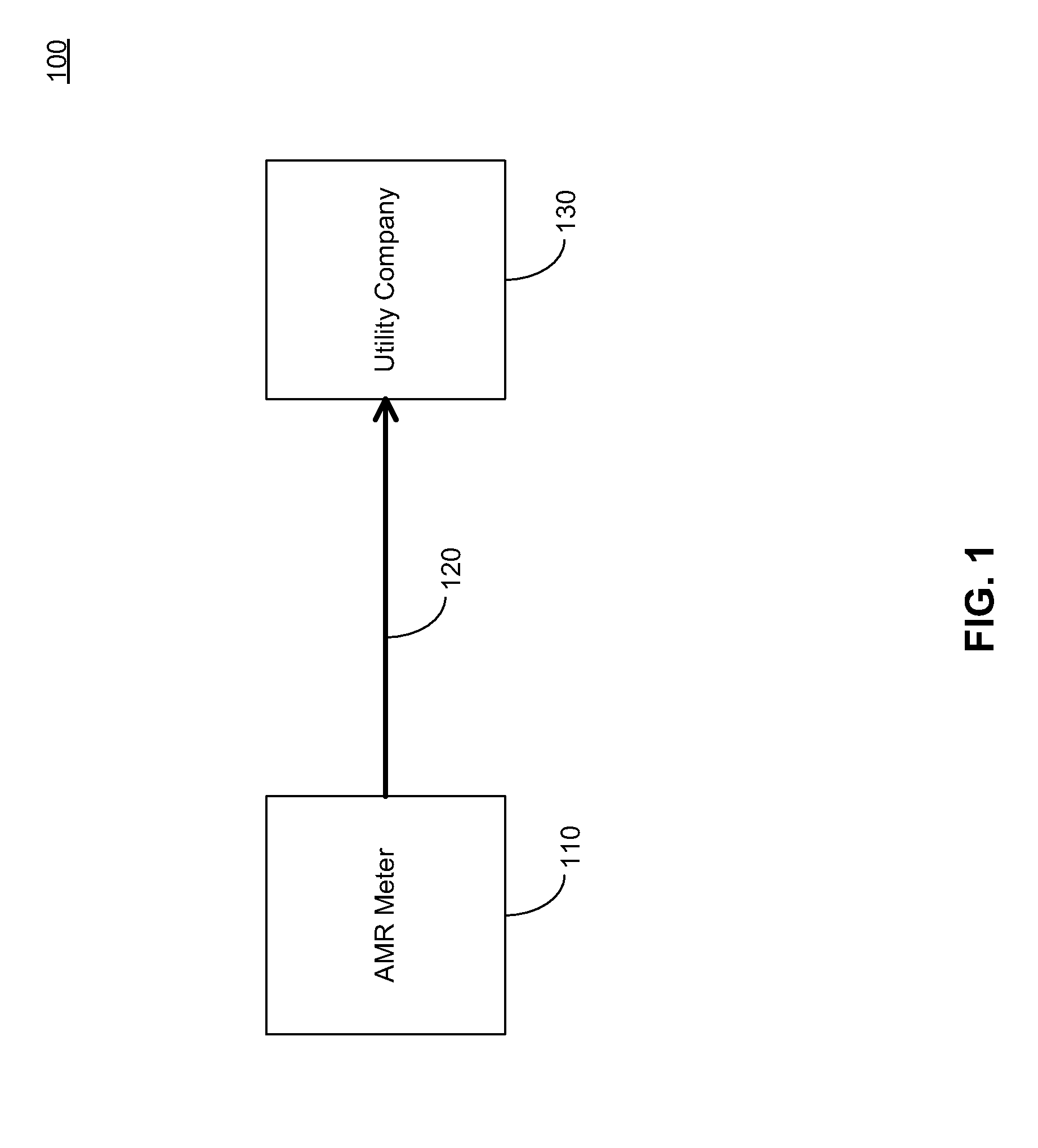
[0032]FIG. 1 depicts an AMR meter-based infrastructure 100. AMR meter 110 measures usage of the utility's commodity (e.g., electricity, water, gas) and displays the cumulative usage on its display to facilitate visual reading. In addition, AMR meter 110 communicates usage to a utility company 130 through an AMR communications path 120. AMR communications path 120 can include a handheld device, drive-by a utility employee or by a fixed network (e.g., mesh network). The handheld device, utility employee and the fixed network use na...


PUM


Abstract

The present application is directed to a system and method of providing flexible real-time two-way energy control and monitoring between utility providers and consumers. Consumer friendly nodes permit communication of targeted information and control, while permitting the utility provider to remotely communicate and control in a real-time environment. Data collection of and accessibility by a community of utility consumers provides social feedback through comparative usage statistics.

Description

RELATED APPLICATION[0001]This application is related to U.S. Provisional Patent Application No. 61 / 139,090 (“the '090 application”), filed Dec. 19, 2008, entitled “System, Method and Apparatus for Providing Telephony and Digital Media Services”. The contents of the '090 application is incorporated herein in its entirety by reference.BACKGROUND[0002]1. Field of the Invention[0003]The present invention relates to utility metering, and in particular to utility control, monitoring and conservation using real-time communication and feedback through comparative usage statistics.[0004]2. Background Art[0005]Usage measurement by utility providers is a routine process whereby utility providers seek to measure the usage of the commodity involved (e.g., water, gas, electricity) by each consumer. Consumers are then billed based on their usage at periodic times, typically monthly. Traditionally, usage was measured manually by utility workers who visited each point-of-use location and read the ut...

Claims


Application Information

Patent Timeline
Patent Type & Authority Applications(United States)
IPC IPC(8): G08C15/06
CPCG01D4/004Y02B90/242Y02B90/244Y04S20/322G06F3/0484Y04S20/44Y04S20/46G05D23/1919Y04S20/327G01D2204/12G01D2204/16G01D2204/18Y02B70/30Y04S20/244G01D4/00G01D9/00Y02B90/20Y04S20/30
Inventor KRZYZANOWSKI, PAULBARCLAY, DAVID
Owner VMWARE INC
Why Eureka
Try Eureka