Diaphragm for an electroacoustic transducer, and electroacoustic transducer

a technology of diaphragm and electroacoustic transducer, which is applied in the direction of transducer diaphragm, loudspeaker diaphragm shape, instruments, etc., to achieve the effect of improving the action mode and the properties of the diaphragm

Inactive Publication Date: 2010-06-24
SOUND SOLUTIONS INTERNATIONAL COMPANY LTD
View PDF8 Cites 3 Cited by
  • Summary
  • Abstract
  • Description
  • Claims
  • Application Information

AI Technical Summary

Benefits of technology

[0004]The object of the invention is to improve the mode of action and the properties of a diaphragm o...

Problems solved by technology

Such a design is customary in general, but has disadvantages with regard to achieving the best possible acoustic propertie...

Method used


Image

  • Diaphragm for an electroacoustic transducer, and electroacoustic transducer
  • Diaphragm for an electroacoustic transducer, and electroacoustic transducer
  • Diaphragm for an electroacoustic transducer, and electroacoustic transducer

Examples


Embodiment Construction

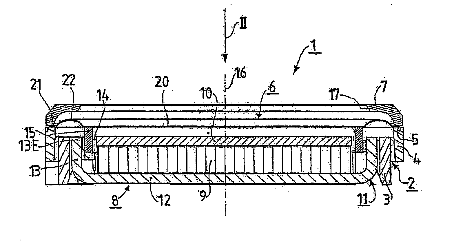
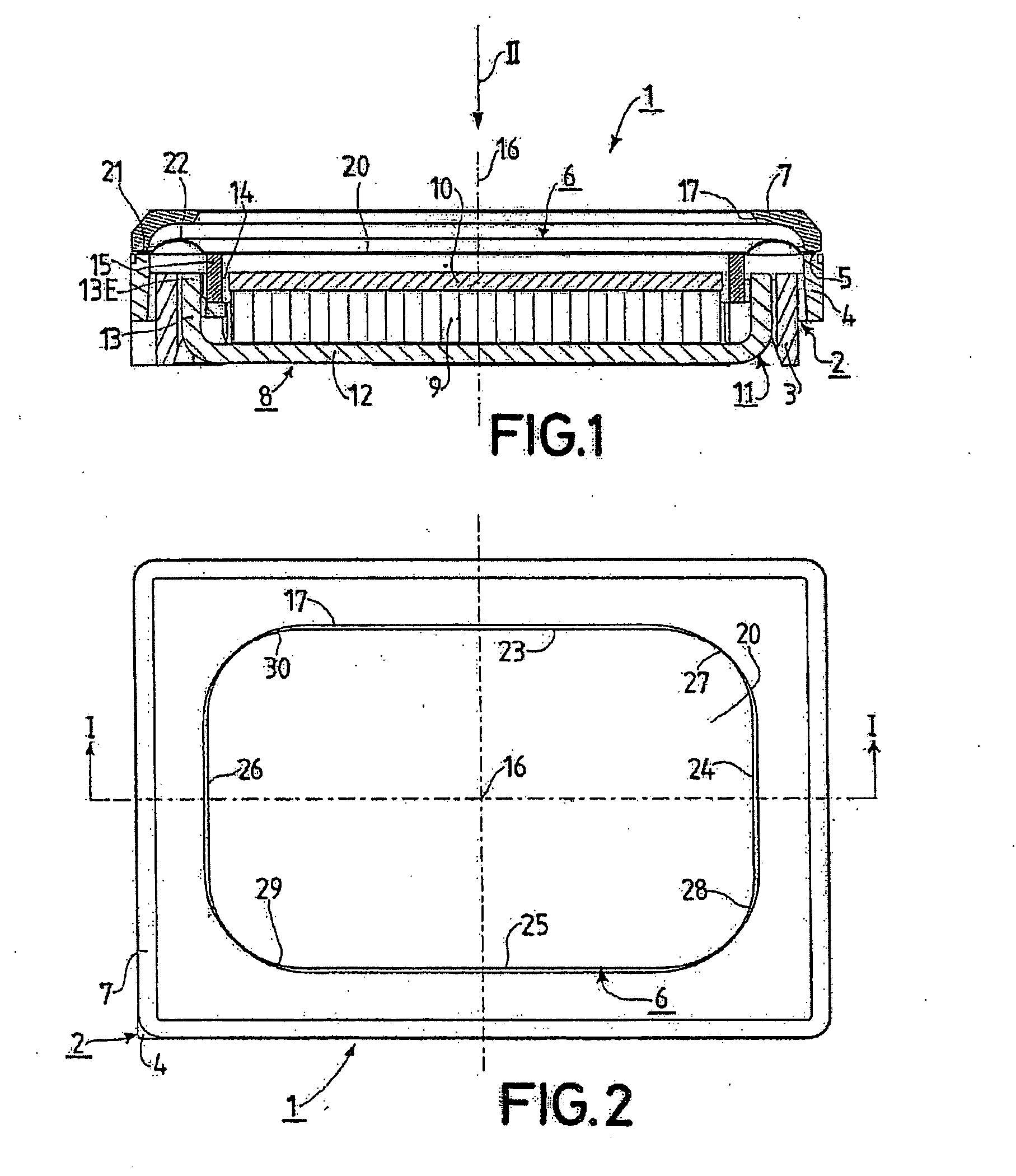
[0025]FIGS. 1 and 2 show an electroacoustic transducer 1 which is designed as a loudspeaker. The electroacoustic transducer 1 will be referred to below as transducer 1 for short. The transducer 1 is designed according to the invention, as will be discussed in more detail below. The transducer 1 has essentially a rectangular shape, but with rounded corner regions instead of sharp corners.

[0026]The transducer 1 has a housing 2. The housing 2 consists of an inner housing region 3 which is essentially hollow-cylindrical, and of an outer housing region 4 which is also essentially hollow-cylindrical, wherein the two housing regions 3 and 4 each have an essentially rectangular cylinder base. The two housing regions 3 and 4 are made of plastic and are produced in one piece. The outer housing region 4 has an annular fixing flange 5 which corresponds to the rectangular shape of the transducer 1 and is provided for attaching a diaphragm 6 of the transducer 1. In order to protect the diaphragm ...


PUM


Abstract

A diaphragm (6) for an electroacoustic transducer is preferably designed to be essentially rectangular and has a diaphragm inner region (20) for sound conversion and a diaphragm outer region (21) for attaching the diaphragm (6) and a diaphragm intermediate region (22) which lies between the diaphragm inner region (20) and the diaphragm outer region (21), wherein the diaphragm inner region (20) is delimited toward the outside by preferably rectilinear sides (23, 24, 25, 26) and the diaphragm outer region (21) is delimited toward the inside again by preferably rectilinear sides (31, 32, 33, 34), and wherein the aforementioned sides (23, 24, 25, 26) of the diaphragm inner region (20) are joined to rounded outer corner regions (27, 28, 29, 30) with a mean outer radius value R and the aforementioned sides (31, 32, 33, 34) of the diaphragm outer region (21) are joined to rounded inner corner regions (35, 36, 37, 38) with a mean inner radius value r, wherein the mean inner radius value r of each inner corner region (35, 36, 37, 38) is smaller than the mean outer radius value R of the opposite outer corner region (27, 28, 29, 30).

Description

FIELD OF THE INVENTION[0001]The invention relates to a diaphragm for an electroacoustic transducer, wherein the diaphragm has a diaphragm inner region and a diaphragm outer region and a diaphragm intermediate region which connects the diaphragm inner region and the diaphragm outer region, and wherein the diaphragm inner region is provided for converting between sound waves and electrical signals, and wherein the diaphragm outer region is provided for attaching the diaphragm, and wherein the diaphragm inner region is delimited toward the outside by a certain number of sides which adjoin the diaphragm intermediate region and between in each case two neighboring sides has a rounded outer corner region with a mean outer radius value, and wherein the diaphragm outer region is delimited toward the inside by the same number of sides which adjoin the diaphragm intermediate region and between in each case two neighboring sides has a rounded inner corner region with a mean inner radius value,...

Claims


Application Information

Patent Timeline
IPC IPC(8): H04R9/06H04R7/02
CPCH04R7/16H04R2307/207H04R7/18H04R7/04
Inventor REINECKE, BENJAMIN
Owner SOUND SOLUTIONS INTERNATIONAL COMPANY LTD
Why Eureka
Try Eureka