SATA connector capable of transmitting electric power

Active Publication Date: 2010-06-24
APACER
View PDF2 Cites 8 Cited by
  • Summary
  • Abstract
  • Description
  • Claims
  • Application Information

AI Technical Summary

Benefits of technology

[0007]Therefore, it is an objective of the present invention to overcome the shortcomings of the prior art by providing a SATA connector capable of transmitting electric power directly, such that the SATA disk module can save the manufacture of a power connector and achieve the effects of making the manufacture of the SATA disk module much easier and lowering the co

Problems solved by technology

Although connectors of this sort divide power and signal transmissions into independent connectors to provide a high sharability of the SATA disk module 10, yet the connectors also incur a complicate

Method used


Image

  • SATA connector capable of transmitting electric power
  • SATA connector capable of transmitting electric power
  • SATA connector capable of transmitting electric power

Examples


Embodiment Construction

[0022]The technical characteristics, features and advantages of the present invention will become apparent in the following detailed description of the preferred embodiments with reference to the accompanying drawings. The drawings are provided for reference and illustration only, but not intended for limiting the present invention.

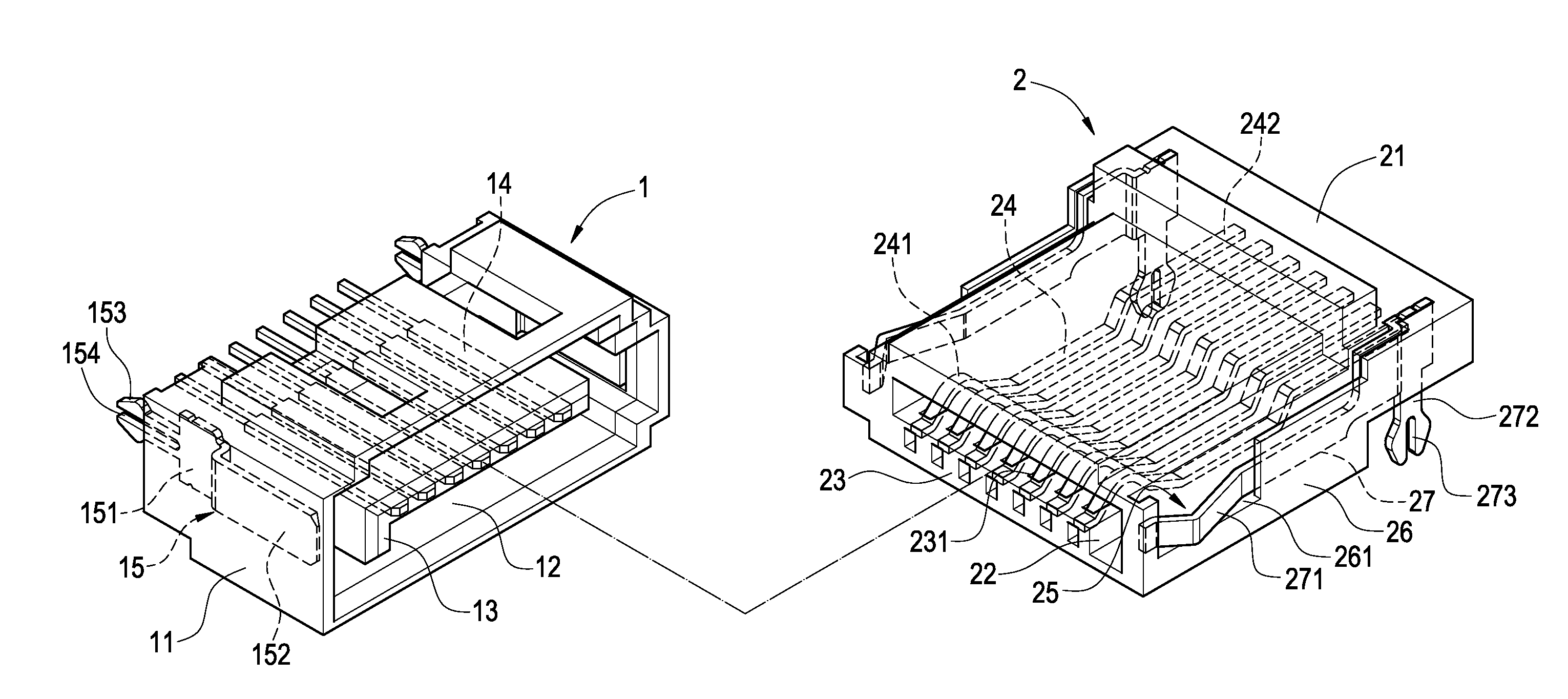
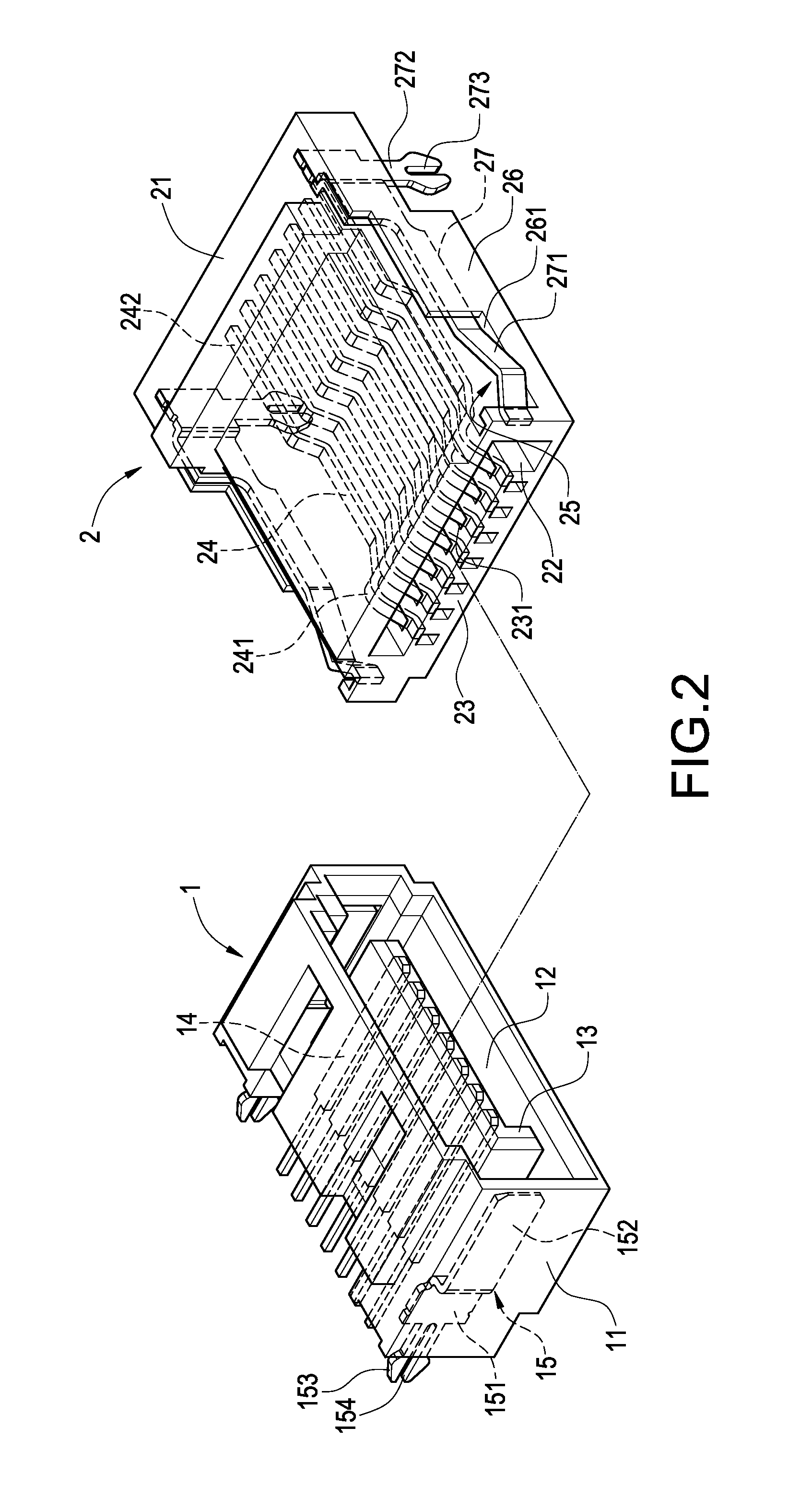
[0023]The present invention provides a SATA female connector for transmitting electric power directly, wherein if a male connector is plugged into the female connector, a first signal pin installed on the female connector is electrically coupled to the male connector and provided for transmitting a SATA signal, and a first power pin is installed onto a sidewall inside the female connector, such that when the male and female connectors are connected, the first power pin is electrically coupled to the male connector for transmitting electric power. The present invention also provides a SATA male connector for transmitting electric power directly, wherein if...


PUM


Abstract

A SATA connector capable of transmitting electric power directly includes female and male connectors. The female connector includes a body and two first power pins. A front end of the body includes a first interface with two sidewalls. An end of the first power pin is disposed on two sidewalls of the first interface, and another end of the first power pin is extended out of a rear end of the body. The male connector includes a body and two second power pins. Both sides of the body have a side groove, and the side groove has an external sidewall. The sidewall includes a notch for exposing an end of the second power pin, and another end of the second power pin is extended out of the body. When the male and female connectors are connected, the second and first power pins constitute an electric connection for transmitting electric power.

Description


Claims


Application Information

Patent Timeline
Owner APACER
Why Eureka
Try Eureka