
Ingrown nail correcting device

a nail and ingrown technology, applied in the field of ingrown nail correcting device, can solve the problems of inability to remove the correcting device from the nail, ineffective force to correct the ingrown nail, and difficulty in removing the correcting device, so as to facilitate the fitting of the correcting device and achieve effective and stable corrective force.

Inactive Publication Date: 2010-06-24
ASO PHARMA CO LTD
View PDF15 Cites 15 Cited by
  • Summary
  • Abstract
  • Description
  • Claims
  • Application Information

AI Technical Summary

Benefits of technology

[0012]This invention is developed in view of the above-mentioned problems. The purpose of this invention is to provide an ingrown nail correcting device which not only facilitates fitting of the correcting device to the ingrown nail but also corrects the ingrown nail while exerting the effective and stable corrective force on the ingrown nail over a long period of time by applying leverage.

Problems solved by technology

Therefore, the force does not work effectively to correct the ingrown nail, which represents a problem.
According to the ingrown nail correcting device made of the shape-memory alloy or the shape-memory resin as described in the Patent Document 2, when the adhesive force of the adhesive agent for bonding the correcting device to the dorsum of the nail is weak, the correcting device is easily removed from the dorsum of the nail and the correction cannot be performed.
On the other hand, when the adhesive force is strong, removal of the correcting device from the nail becomes difficult, which is also a problem.
In addition, since the correcting device needs to be heated by a dryer or warm water to correct the ingrown nail, it is difficult to exert the corrective force continuously for a long time, and the correction cannot be performed as well when heating is stopped as the correcting device returns into the original shape, which also represents a problem.
However, even when the correcting device is fixed onto the upper face of the nail by the adhesive tape in the state that the engaging member part may hook the front end part of the ingrown nail, the engaging member part hardly has a sufficient corrective force for pulling the ingrown nail up.
Thus, an effective corrective force cannot be obtained, which represents a problem.

Method used


Image

  • Ingrown nail correcting device
  • Ingrown nail correcting device
  • Ingrown nail correcting device

Examples


first embodiment

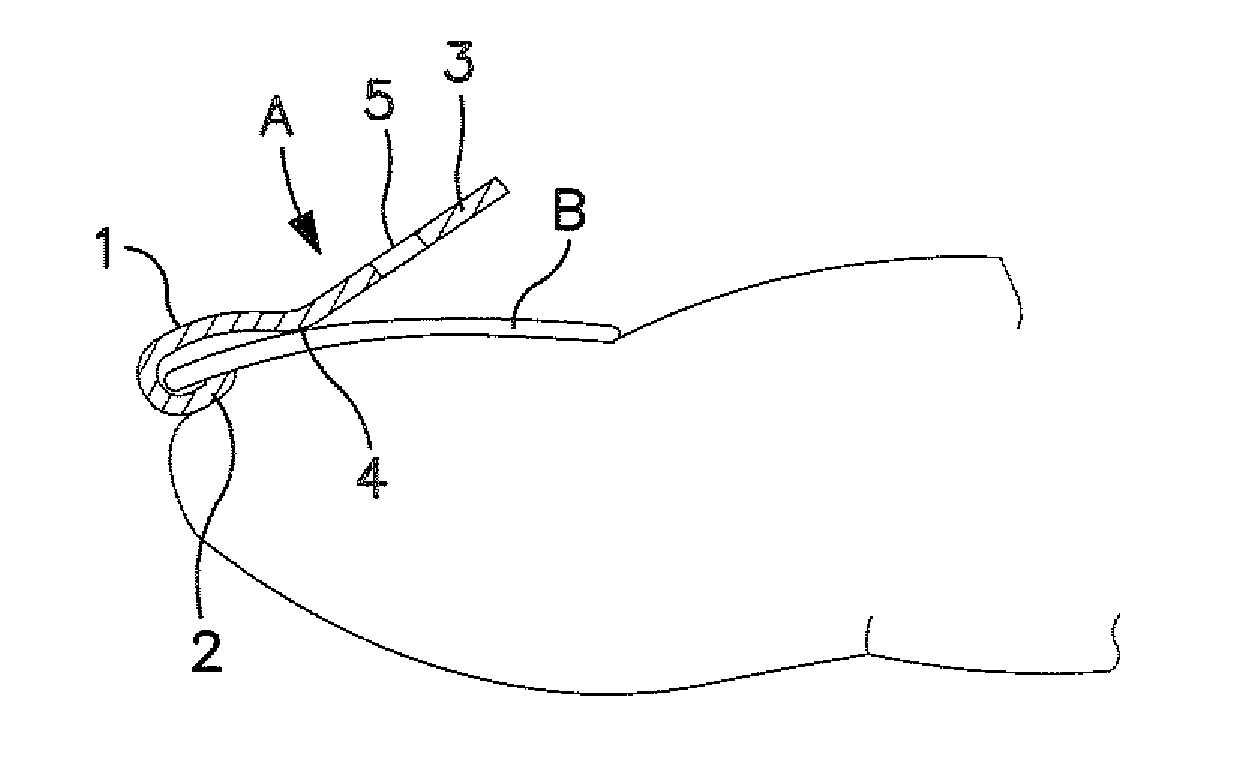
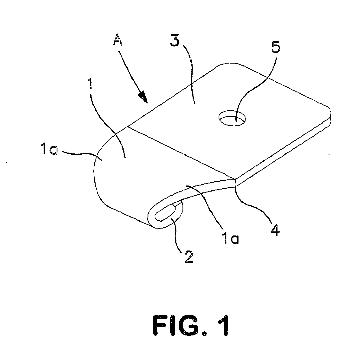
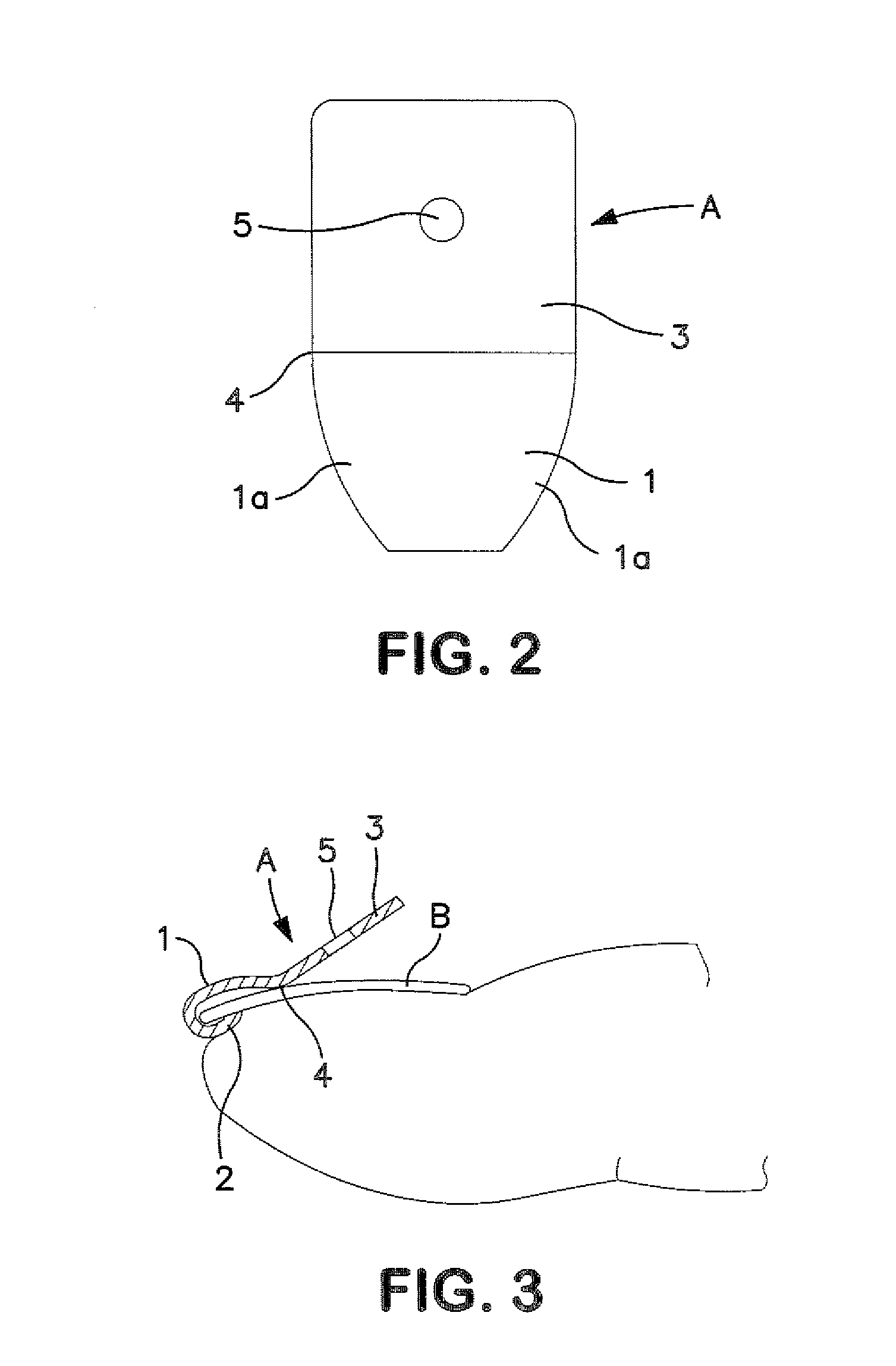
[0034]the present invention is explained hereinafter based on the drawings. As shown in FIGS. 1 and 2, the ingrown nail correcting device A comprises the ingrown nail correcting device main body 1, of which the length in front and back direction is formed to be a little longer than the length from the front end to the base end of the nail B and the lateral width of a base end part thereof is formed to be ½ to ⅓ of lateral width of the nail B, an engaging member part 2 which is formed at the front end of the main body 1 in a manner of being folded backward and extending under the main body 1 to form a hook-like shape, and a lever member 3 which has a flat rectangular plate-like shape and gently inclines obliquely upward from the base end part of the main body 1 in the rear direction. A joint part of the base end of the main body 1 and the front end of the lever member 3 is formed to be a fulcrum part 4. Further, a lower face of the engaging member part 2 and a lower face of the lever...

second embodiment

[0045]this invention is explained hereinafter based on the drawings. FIG. 8 shows a perspective view of an ingrown nail correcting device main constituent, FIG. 9 shows a perspective view of the ingrown nail correcting device in use, and FIG. 10 shows a perspective view of the state of use. The ingrown nail correcting device main constituent 11 is formed of a thin rectangular metal plate or a hard and thin synthetic resin plate both having resilience. A longitudinal center of the thin plate is bent downward into a V-letter shape to form a fulcrum part 12. A front side of the fulcrum part 12 is formed to be an ingrown nail correcting element 13 and a rear side thereof is formed to be a lever member 14 which extends obliquely upward from a base end (a rear end) of the correcting element 13 in an extending direction of the correcting element 13. Further, a front end part of the correcting element 13 is folded down and then back to form a hook-shaped engaging member 15 to hook a front e...

third embodiment

[0053]this invention is described hereinafter based on the drawings. In FIGS. 13 to 15, the correcting device for the ingrown nail A including a curved nail deformed to have a wavy front end comprises a correcting device main constituent 21 formed of a thin rectangular metal plate or a hard and thin synthetic resin plate, both having resilience, a correcting member 26 connected to a front end of the main constituent 21 in a manner that it can be engaged and disengaged, and a fixing member 30 like an adhesive tape for fixing the main constituent 21 onto the dorsum of the toe or the finger.

[0054]The main constituent 21 is formed to have a bent fulcrum part 22 by bending a longitudinal center part or the part closer to the front from the center part of the resilient rectangular thin plate downward into a V-letter shape. The front half from the bent fulcrum part 22 to the front end is formed to be an acting member 23 inclined obliquely upward from the bent fulcrum part 22 to the front e...


PUM


Abstract

The ingrown nail correcting device made of a resilient hard synthetic resin comprises an ingrown nail correcting device main body, an engaging member part curved into a hook shape to engage the ingrown nail and arranged at the front end of the ingrown nail correcting device main body, and a lever member inclined obliquely upward at an angle of 5 to 25 degrees with respect to the ingrown nail correcting device main body, and continuously arranged at a base end of the ingrown nail correcting device main body. The part between the ingrown nail correcting device main body and the lever member which are continuously arranged, is formed to serve as a fulcrum part.

Description

BACKGROUND OF THE INVENTION[0001]1. Field of the Invention[0002]This invention relates to an ingrown nail correcting device for correcting an ingrown nail by being fitted to a toe or a finger, or particularly to a big toe or a thumb having an ingrown nail.[0003]2. Description of the Prior Art[0004]Ingrown nail correcting devices of various shapes and structures have been developed so far. Such conventional ingrown nail correcting devices include, for example, an ingrown nail correcting device comprising an elastic correcting member having rubber elasticity or a resilient metal plate which is provided with hook-shaped engaging members on both longitudinal side-ends thereof to hook both side-ends of the ingrown nail, as described in the Patent Document 1, an ingrown nail correcting device made of a shape-memory alloy or a shape-memory resin which is bonded onto a dorsum of the nail and heated to bend the ingrown nail in the correcting direction, as described in the Patent Document 2, ...

Claims


Application Information

Patent Timeline
Patent Type & Authority Applications(United States)
IPC IPC(8): A61F5/00
CPCA61F5/11
Inventor YOSHIKAWA, MASANORI
Owner ASO PHARMA CO LTD
Learn More