Reinforced closure anchor

a technology of closure and anchor, which is applied in the field of medical dressings, can solve the problems of increased nursing costs, difficult dressing and/or removal, and bulky and cumbersome, and achieve the effects of preventing inadvertent peeling, reducing the amount of fabric cloth stretching, and multiplying the dressing withstand

Active Publication Date: 2010-06-24
MEDLINE IND LP
View PDF13 Cites 5 Cited by
  • Summary
  • Abstract
  • Description
  • Claims
  • Application Information

AI Technical Summary

Benefits of technology

[0005]The present invention provides a reinforced closure anchor that can close over and anchor a slit, perforation, notch, or edge portion of a medical dressing at which a catheter and / or tubing exits from underneath the dressing. The reinforced closure anchor helps prevent a dressing from inadvertently peeling from a patient's skin, which may be caused by tugging on tubing that is under and exiting from the dressing, by both covering over a portion of the medical dressing and by securing an area of the dressing at which medical tubing exits from underneath the dressing. The reinforced closure anchor also prevents inadvertent peeling by providing additional material beyond the dressing edge, thereby greatly multiplying the dressing withstand in tug force vector directions opposite to (and at any relative angle to, over an entire hemispherical (half globe) field of tug force vectors) that which tubing exits from the dressing. Also, the reinforced closure anchor limits the amount of fabric cloth stretching that can occur by using relatively non-elastic reinforcement material for a spinal structure, which limits the amount and size of a “hole” that can be stretched open by tugs, and thus prevents catheter hubs and / or tubing from “oozing” out of a dressing. And due to the narrow spinal structure's limited portion of entire closure's surface area, higher moisture vapor transmission rate is possible over as much as 90 to 95 percent of the closure's total skin contacting and dressing overlapping surface area.

Problems solved by technology

These securement devices, however, are often bulky and cumbersome, hard to dress and / or remove with a dressing, may require a scissors or scalpel to physically cut them away risking catheter lumen or catheter pigtails damage in the process, may require two, three, or four pieces of tape to get reliable results, and may have costly and complex mechanical features; all of which can combine to both lower patient care clinical outcomes, and equally important, lead to higher healthcare costs due to added nursing costs.
It is also known in the medical field that poorly dressed and poorly secured catheters and associated tubing are likely to undesirably lead to irritation of both internal vascular wall damage at distal catheter tip due to in / out catheter tip motion at the insertion site, necessitating premature rotation and reinsertion of the catheter to a nearby new anatomical insertion site.
Even worse, poorly secured catheters are susceptible to accidental dislodgement from the insertion site.
For example, medical tubing connected to indwelling catheters, infusion needles and the like is often subjected to inadvertent but significant pulling forces either caused directly by patient movement or by snagging of the tubing on other objects.
This exposes the catheter, infusion needle, etc. to movement inward or outward, increasing the likelihood that the catheter, infusion needle, etc. will fail and have to be replaced and inserted into a new insertion site.
Also, this may weaken the adhesion between the dressing and the patient's skin, potentially exposing the insertion site to harmful bacteria.

Method used


Image

  • Reinforced closure anchor
  • Reinforced closure anchor
  • Reinforced closure anchor

Examples


Embodiment Construction

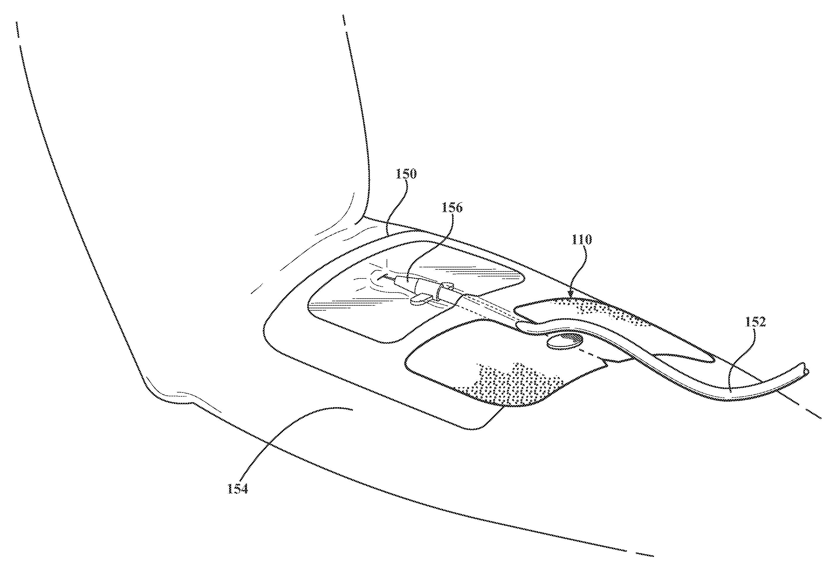
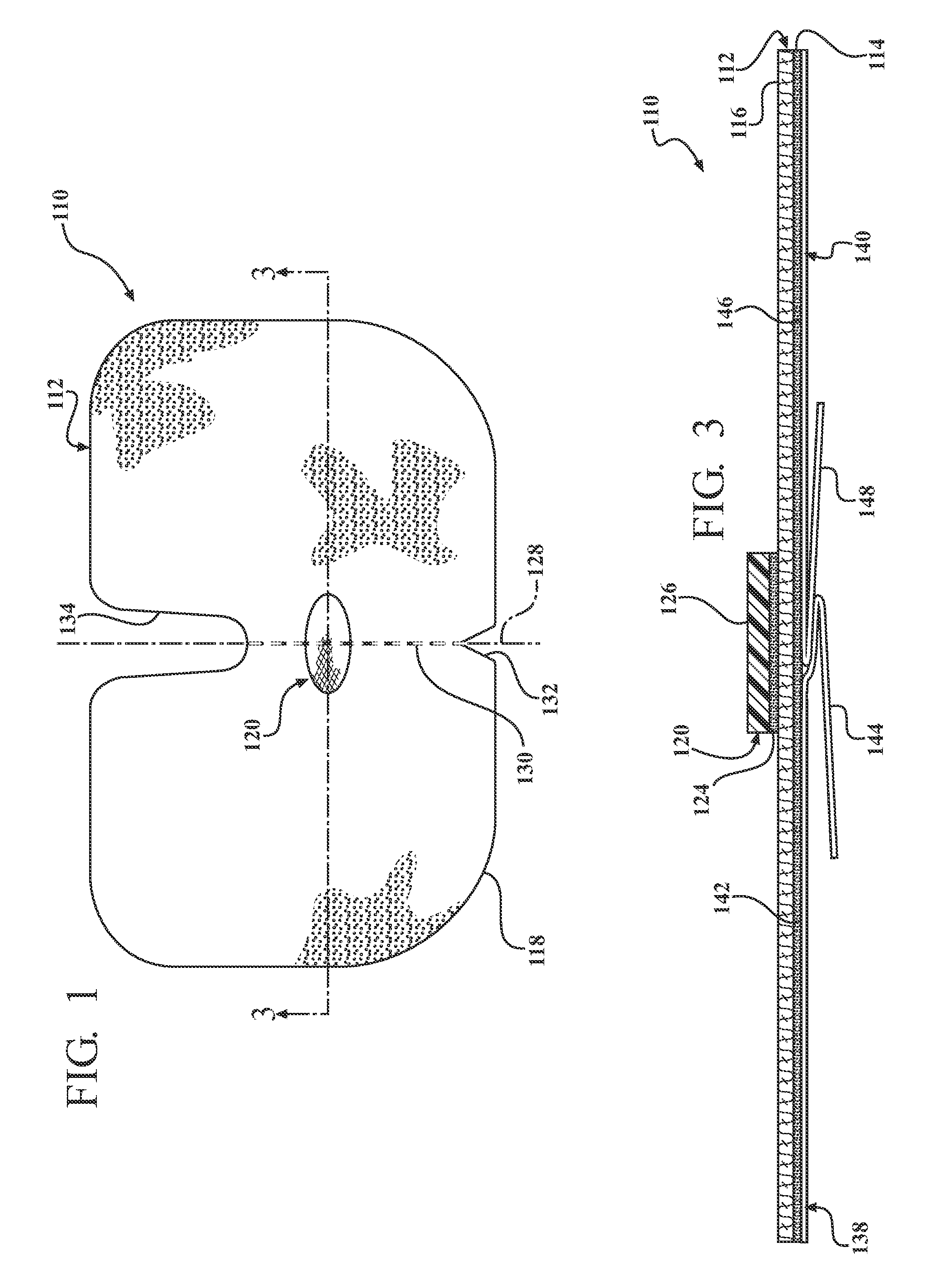
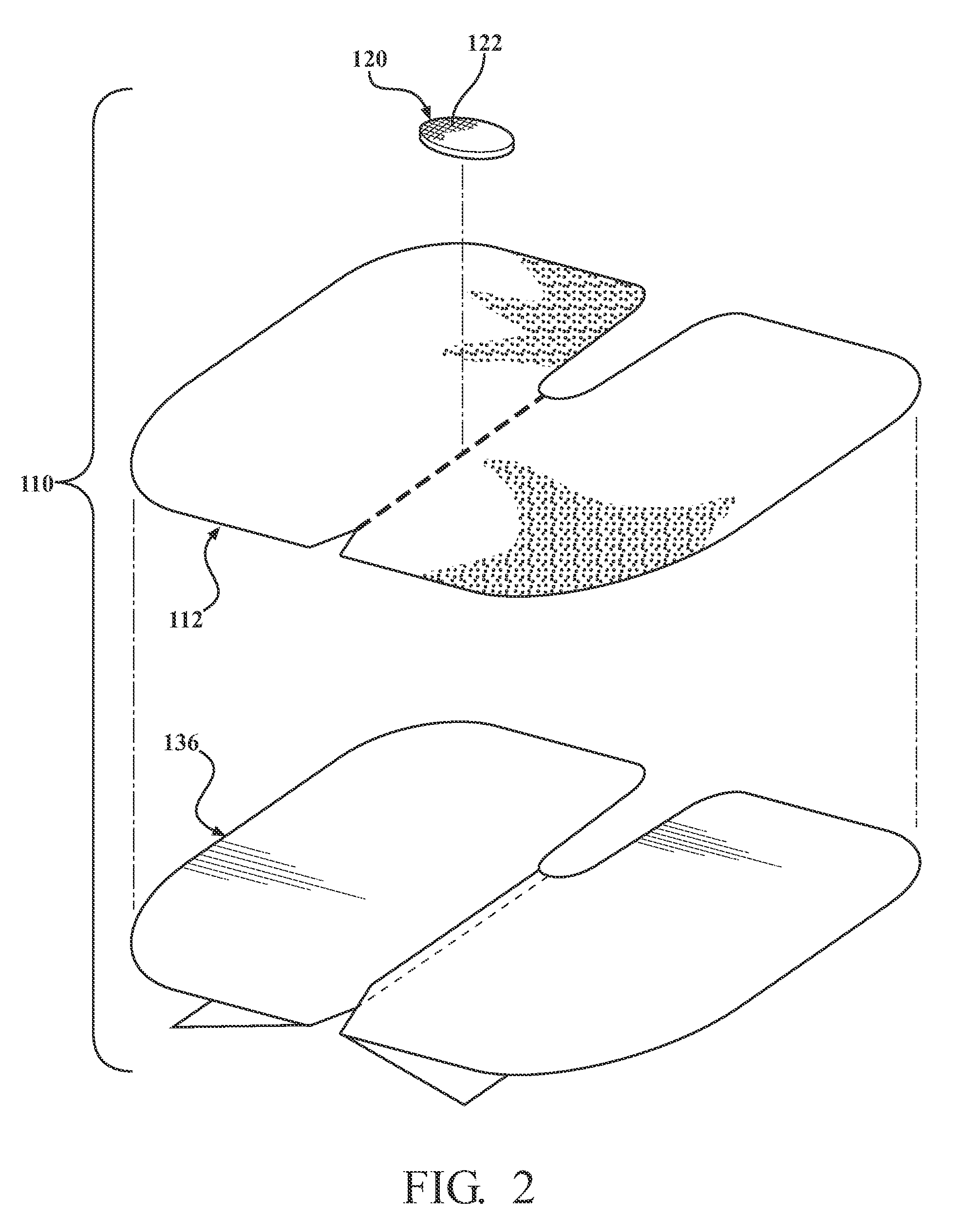
[0033]Referring now to the drawings in detail, numeral 110 generally indicates a reinforced closure anchor in accordance with the invention. The reinforced closure anchor 110 may secure a portion of a medical dressing, such as a portion at which medical tubing exits from underneath the dressing. The reinforced closure anchor 110 counteracts tugging forces from any hemispherical vector direction that may be applied on the medical tubing and helps prevent the tugging forces from pulling the dressing away from a patient's skin.

[0034]Turning to FIGS. 1 through 3, the reinforced closure anchor 110 includes a first layer 112 having an adhesive side 114 including an adhesive such as a medical skin contact grade adhesive or similarly suitable adhesive thereon. The first layer 112 also has an opposite non-adhesive side 116 and an outer edge 118. The first layer 112 is not limited to any particular shape. In the embodiment shown in the drawings, the first layer 112 is generally rectangular in...


PUM


Abstract

A reinforced closure anchor includes a first layer having an adhesive side, an opposite non-adhesive side, and an outer edge. An anchor member layer having a reinforcing structure is disposed on the first layer. The anchor member includes an adhesive side and an opposite non-adhesive side. The anchor member adhesive side is adhered to the first layer non-adhesive side or the first layer adhesive side. The anchor member is disposed within the outer edge of the first layer. The anchor member may have a surface area that is in the range of approximately 1-2% of a surface area of the first layer, or the anchor member may have a surface area that is in the range of approximately 99-100% of a surface area of the first layer.

Description

CROSS REFERENCE TO RELATED APPLICATIONS[0001]This application is a continuation of U.S. patent application Ser. No. 12 / 690,315, filed Jan. 20, 2010, which is a continuation-in-part of U.S. patent application Ser. No. 12 / 558,634, filed Sep. 14, 2009, which is a continuation of U.S. patent application Ser. No. 12 / 011,692, filed Jan. 29, 2008.TECHNICAL FIELD[0002]This invention relates to medical dressings, and more particularly to reinforced closure members for closing a portion of a medical dressing and anchoring medical tubing.BACKGROUND OF THE INVENTION[0003]It is known in the art relating to medical dressings for the protection and securement of catheters to apply a dressing to a patient's skin to cover a catheter insertion site at which the catheter punctures a patient's skin. It is also common for medical clinicians (i.e., doctors, nurses, and other medical personnel) to alternatively or additionally apply strips of medical grade tape to attempt to secure the catheter or associa...

Claims


Application Information

Patent Timeline
Patent Type & Authority Applications(United States)
IPC IPC(8): A61M25/02
CPCA61F2013/00451A61M2025/0273A61M25/02
Inventor PROPP, DONALD J.
Owner MEDLINE IND LP
Why Eureka
Try Eureka