Variable weave graft with metal strand reinforcement for in situ fenestration

a technology of in situ fenestration and weave graft, which is applied in the field of weave graft with metal strand reinforcement for in situ fenestration, can solve the problems of inability to fend off incisions, blood vessel failure, and defected vasculature, and achieves undesirable invasive methods

Active Publication Date: 2010-06-24
COOK MEDICAL TECH LLC
View PDF56 Cites 62 Cited by
  • Summary
  • Abstract
  • Description
  • Claims
  • Application Information

AI Technical Summary

Benefits of technology

[0007]In another example, an implantable prosthesis for treatment of a main vessel defect near one or more branch vessels is provided. The prosthesis comprises a graft comprising textile strands aligned in a first direction interwoven with textile strands and metal strands aligned in a second direction. The woven strands define a lumen with a proximal end and a distal end. The graft further comprises a main portion and at least one passage disposed between the proximal and distal end. The metal strands are aligned with the at least one passage and woven in at least the main portion. Although at least some textile strands traverse the at least one passage, the passage is defined by having a lower weave density than the main portion.

Problems solved by technology

Aneurysms occur in blood vessels in locations where, due to age, disease or genetic predisposition, the blood vessel strength or resiliency is insufficient to enable the blood vessel wall to retain its shape as blood flows therethrough, resulting in a ballooning or stretching of the blood vessel at the limited strength / resiliency location to thereby form an aneurysmal sac.
If the aneurysm is left untreated, the blood vessel wall may continue to expand, to the point where the remaining strength of the blood vessel wall is below that necessary to prevent rupture, and the blood vessel will fail at the aneurysm location, often with fatal result.
In many cases, however, the damaged or defected portion of the vasculature may include a branch vessel.
Such invasive methods, however, are undesirable.
However, inaccuracies in the location of fenestrations may occur due to the unique vasculature and location of branch vessels in each patient.

Method used


Image

  • Variable weave graft with metal strand reinforcement for in situ fenestration
  • Variable weave graft with metal strand reinforcement for in situ fenestration
  • Variable weave graft with metal strand reinforcement for in situ fenestration

Examples


Embodiment Construction

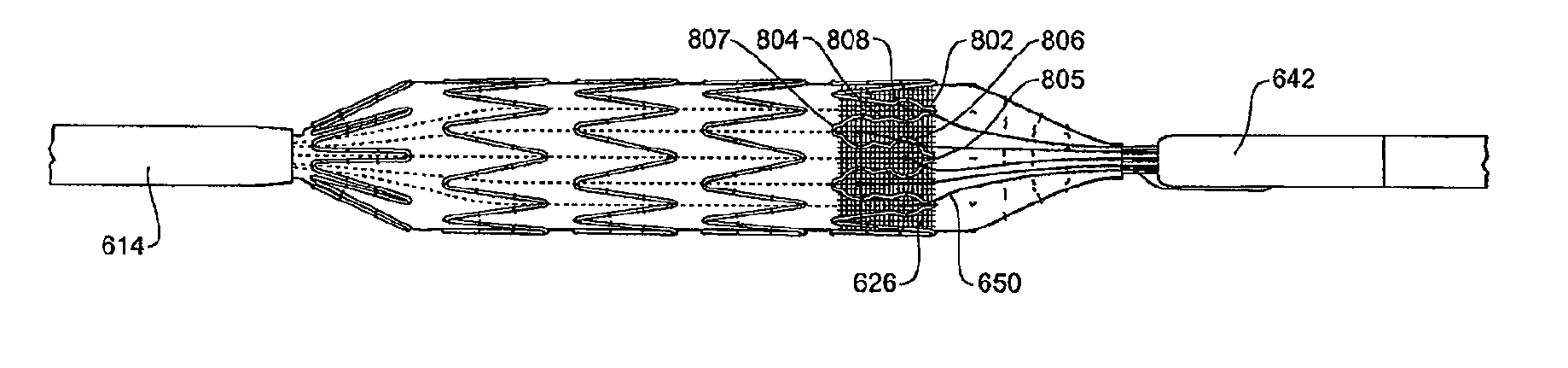
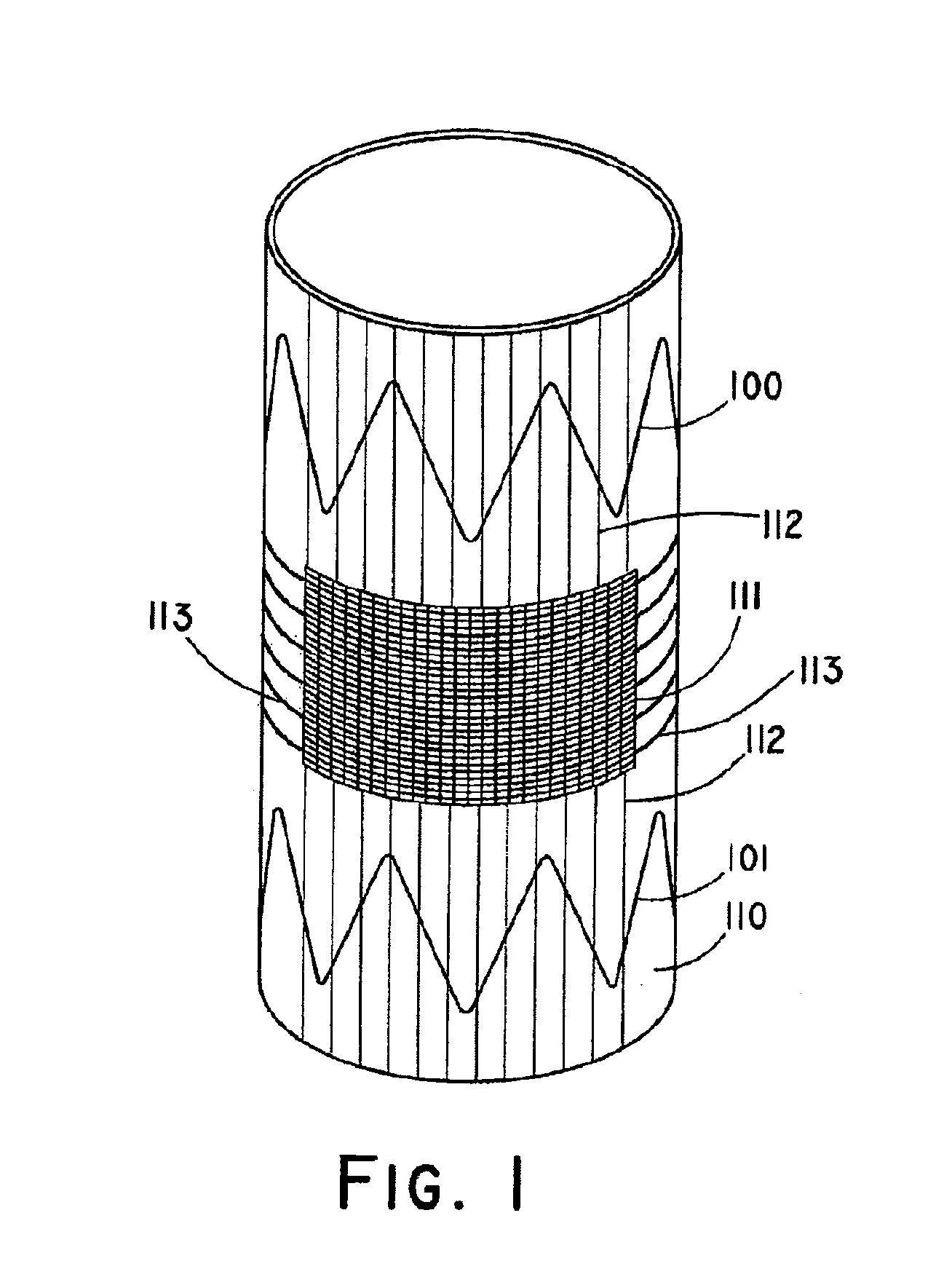
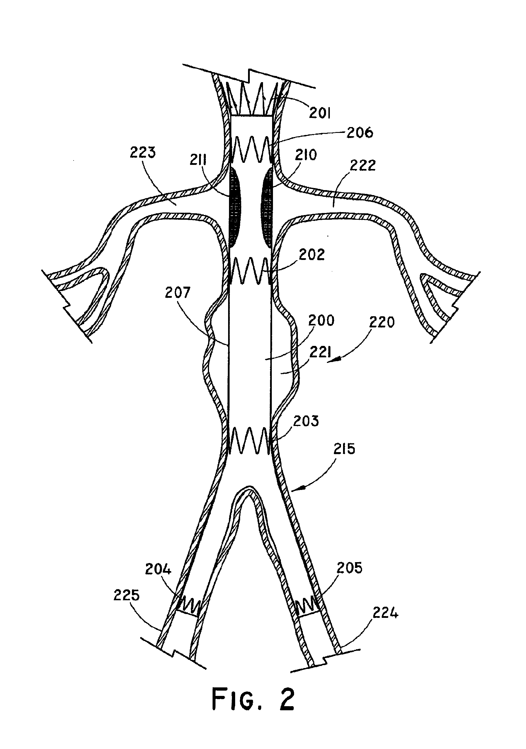
[0019]The present disclosure provides for a variable weave graft having a reduced density region for bridging a defect in a main vessel near one or more branch vessels. Unless otherwise defined, all technical and scientific terms used herein have the same meaning as commonly understood by one of ordinary skill in the art to which this disclosure pertains. In case of conflict, the present document, including definitions, will control. Preferred methods and materials are described below, although methods and materials similar or equivalent to those described herein can be used in the practice or testing of the present disclosure. All publications, patent applications, patents and other references mentioned herein are incorporated by reference in their entirety. The materials, methods, and examples disclosed herein are illustrative only and not intended to be limiting.

Definitions

[0020]The term “implantable” refers to an ability of a medical device to be positioned at a location within ...


PUM

PropertyMeasurementUnit
densityaaaaaaaaaa
weave densityaaaaaaaaaa
strengthaaaaaaaaaa

Abstract

The disclosure relates to an implantable woven graft for bridging a defect in a main vessel near one or more branch vessels. The graft includes a region of reduced density. Reduced density regions are alignable with at least one of the one or more branch vessels, and are suitable for in situ fenestration, for example by perforation. The disclosed examples are particularly suited for bridging abdominal aortic aneurysms.

Description

PRIORITY CLAIM[0001]This application claims the benefit of provisional U.S. Patent Application Ser. No. 61 / 092,996, filed Aug. 29, 2008, which is incorporated herein by reference in its entirety.BACKGROUND OF THE INVENTION[0002]Aneurysms occur in blood vessels in locations where, due to age, disease or genetic predisposition, the blood vessel strength or resiliency is insufficient to enable the blood vessel wall to retain its shape as blood flows therethrough, resulting in a ballooning or stretching of the blood vessel at the limited strength / resiliency location to thereby form an aneurysmal sac. If the aneurysm is left untreated, the blood vessel wall may continue to expand, to the point where the remaining strength of the blood vessel wall is below that necessary to prevent rupture, and the blood vessel will fail at the aneurysm location, often with fatal result.[0003]To prevent rupture, a stent graft of a tubular construction may be introduced into the blood vessel, for example i...

Claims


Application Information

Patent Timeline
Patent Type & Authority Applications(United States)
IPC IPC(8): A61F2/06A61F2/82
CPCA61F2/07A61F2220/0075A61F2/954A61F2002/061A61F2002/075A61F2002/8483A61F2002/9517A61F2210/0004A61F2220/0016A61F2250/0017A61F2250/0067A61F2250/0071A61F2250/0098A61F2/89A61F2220/005A61F2220/0058A61F2/95A61F2/9517
Inventor KUPPURATHANAM, SHYAMBIGGS, DAVID P.IVANCEV, KRASNODARHARRIS, PETER
Owner COOK MEDICAL TECH LLC
Why Eureka
Try Eureka