Quick test tool and method of aircraft airspeed indicator

a technology of airspeed indicator and test tool, which is applied in the direction of volume/mass flow by differential pressure, instrument, testing/calibration for volume flow, etc. it can solve the problems of compromising the safe flight of the aircraft, being complex in its operation, and expensive existing test tools, so as to prevent an aircraft accident, easy to use, and easy to use

Inactive Publication Date: 2010-07-01
KOREA AEROSPACE RES INST
View PDF3 Cites 4 Cited by
  • Summary
  • Abstract
  • Description
  • Claims
  • Application Information

AI Technical Summary

Benefits of technology

[0017]According to embodiments of the present invention, there may be provided a test tool and method for an airspeed indicator of an aircraft that may enable manufacturing of an airspeed indicator test tool at inexpensive costs using an inexpensive material. In addition, since an operation scheme and an operation principle are simple, the test tool may be easily used.
[0018]Also, since it is possible to test an operational state of the airspeed indicator of the aircraft as desired, a malfunction of the airspeed indicator may be identified at an early stage, which may result in preventing an accident with the aircraft.

Problems solved by technology

This is due to an existing test tool being very expensive and—being complex in its operation.
In addition, only a skilled person having completed courses of an airspeed test education may operate the test tool.
Since the airspeed indicator may not be tested at all desired times, a malfunction of the airspeed indicator may not be identified at an early stage and damage to the airspeed indicator may go undetected, which may result in compromising a safe flight of the aircraft.
Also, since it is possible to test an operational state of the airspeed indicator of the aircraft as desired, a malfunction of the airspeed indicator may be identified at an early stage, which may result in preventing an accident with the aircraft.

Method used


Image

  • Quick test tool and method of aircraft airspeed indicator
  • Quick test tool and method of aircraft airspeed indicator
  • Quick test tool and method of aircraft airspeed indicator

Examples


Embodiment Construction

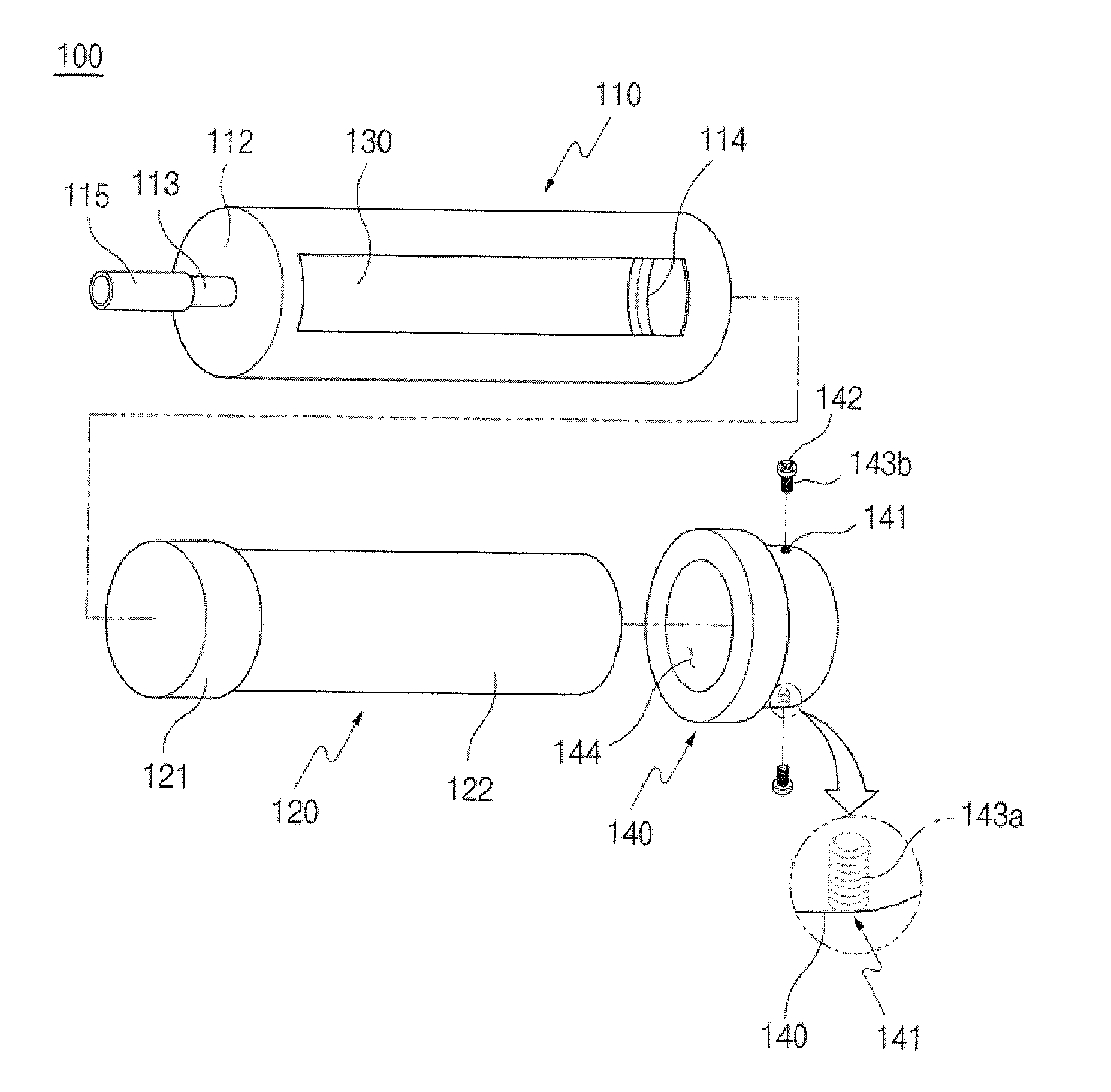
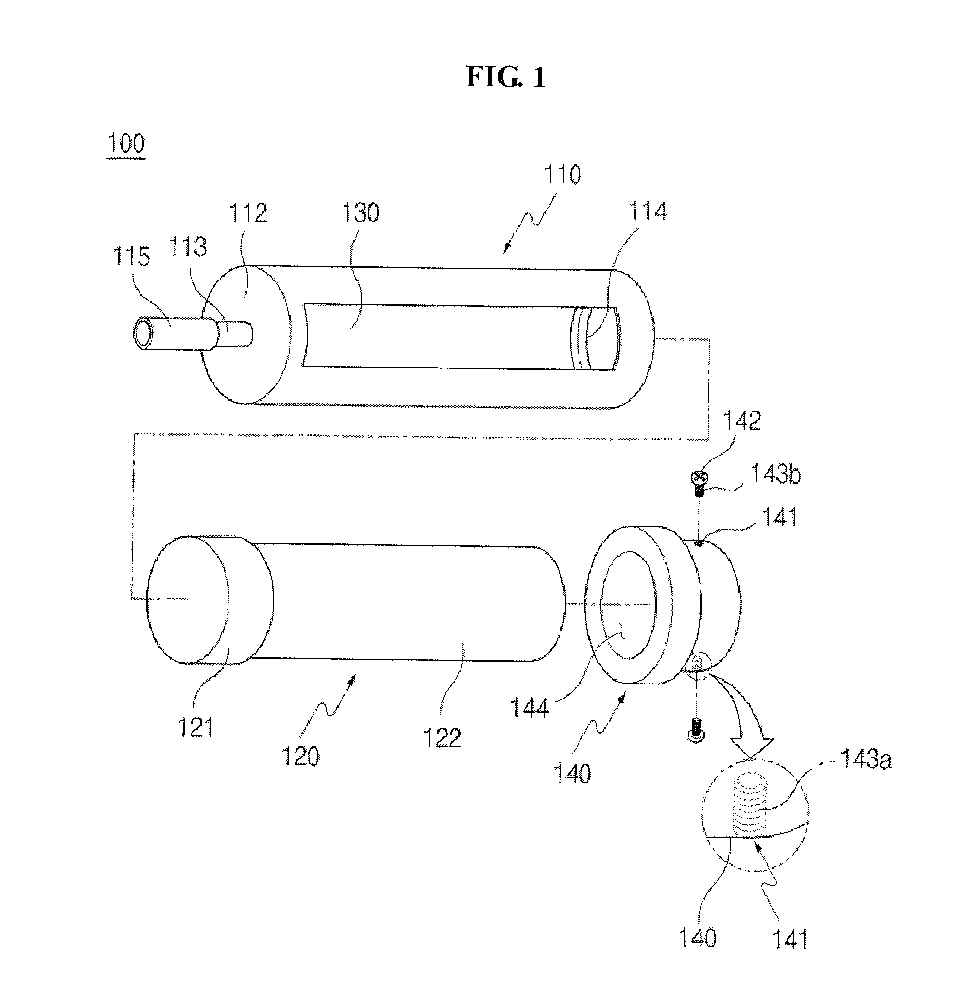
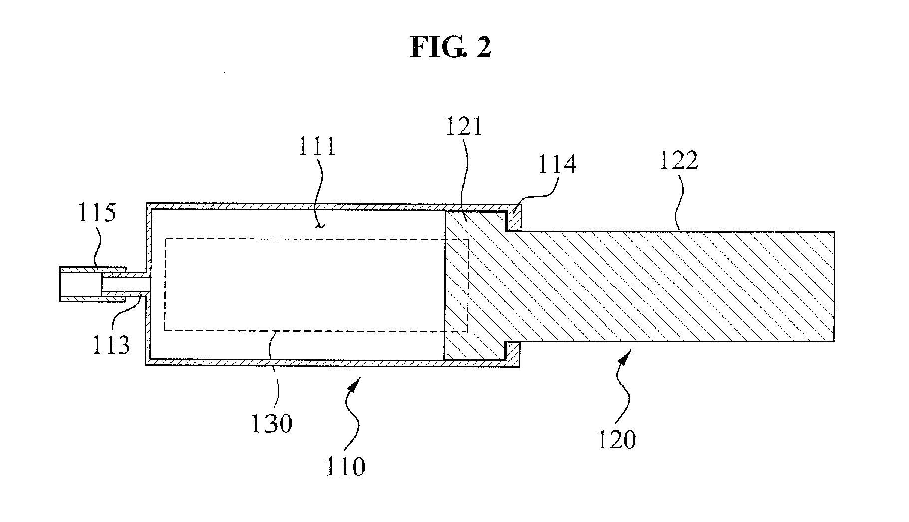
[0024]Reference will now be made in detail to exemplary embodiments of the present invention, examples of which are illustrated in the accompanying drawings, wherein like reference numerals refer to the like elements throughout. Exemplary embodiments are described below to explain the present invention by referring to the figures.

[0025]Hereinafter, embodiments of the present invention will be described with reference to the accompanying drawings. Terminologies or terms used throughout the present specification or claims should not be interpreted as general or lexical meaning, and may nee to be understood as meaning and concepts corresponding to technical spirit of the invention based on a principle that the inventor may appropriately define the terms to describe the inventor's invention according to a best mode.

[0026]Accordingly, embodiments and drawings of the present invention are only examples and thus may not represent all the technical spirit of the invention.

[0027]Accordingly,...


PUM


Abstract

Provided is a test tool for an airspeed indicator of an aircraft, including: a cylinder portion including an insertion groove with a predetermined amount of space, and of which one end is sealed by a cover and includes an injection portion on the cover so that the insertion groove passes through a pitot tube, and of which another open end includes a protruded step around its inner circumferential surface; a piston portion being inserted into the insertion groove to reciprocally move within the insertion groove, and including a protrusion portion having a size and a shape corresponding to an aperture of the insertion groove, and a bar-shaped knob portion being extended from the protrusion portion; and a display portion being formed of a transparent material on an outer surface of the cylinder portion to display a location of the protrusion portion reciprocally moving within the cylinder portion.

Description

CROSS-REFERENCE TO RELATED APPLICATION[0001]This application claims the benefit of Korean Patent Application No. 10-2008-0138384, filed on Dec. 31, 2008, in the Korean Intellectual Property Office, the disclosure of which is incorporated herein by reference.BACKGROUND[0002]1. Field of the Invention[0003]The present invention relates to a test tool and method for an airspeed indicator to of an aircraft, and more particularly, to a test tool and method for an airspeed indicator of an aircraft that may be connected to a pitot tube of the aircraft to easily test the airspeed indicator of the aircraft using the air pressure of the aircraft.[0004]2. Description of the Related Art[0005]One of the most important instruments for a navigation of an aircraft is an airspeed indicator to provide a pilot with airspeed information of the aircraft.[0006]Generally, airspeed of the aircraft may be calculated using a scheme different from a vehicle velocity calculation scheme. Initially, a velocity of...

Claims


Application Information

Patent Timeline
Patent Type & Authority Applications(United States)
IPC IPC(8): G01F1/46G01P21/00G01M99/00
CPCG01F1/46G01F25/003G01P5/16G01P21/025G01F25/13G01P21/02G01M99/00G01R35/00
Inventor CHANG, JAE WONSEONG, KIE JEONGLEE, SANG JONGMOON, SANG MANKIM, HYOUN KYOUNGPARK, IL KYUNGJEON, BYOUNG HO
Owner KOREA AEROSPACE RES INST
Why Eureka
Try Eureka