Eureka AIR delivers breakthrough ideas for toughest innovation challenges, trusted by R&D personnel around the world.

Sheet storing device and image recording apparatus comprising sheet storing device

Active Publication Date: 2010-07-01
BROTHER KOGYO KK
View PDF8 Cites 10 Cited by
  • Summary
  • Abstract
  • Description
  • Claims
  • Application Information

AI Technical Summary

Benefits of technology

[0008]Therefore, a need has arisen for a sheet storing device and an image recording apparatus that overcome these and other shortcomings of the related art. A technical advantage of the invention is that a tray of the sheet storing device is reliably positioned and retained in a predetermined position with respect to a container of the sheet storing device.
[0009]According to an embodiment of the invention, a sheet storing device comprises a container comprising a first holding surface configured to hold a first sheet thereon, and a tray positioned at an upper side of the container. The tray comprises a second holding surface configured to hold a second sheet thereon. The tray is configured to selectively move between a first position and a second position downstream from the first position in a first direction. The sheet storing device further comprises a positioning unit configured to selectively position the tray in one of the first position and the second position, and a linking unit configured to link the tray to the container and to pivot about a particular pivot axis which extends in a second direction perpendicular to the first direction and parallel to the first holding surface of the container. The linking unit pivots to selectively move the tray between the first position and the second position.
[0010]According to another embodiment of the invention, an image recording apparatus comprises a sheet storing device, a housing, a feed roller, and a recording unit. The sheet storing device comprises a container comprising a first holding surface configured to hold a first sheet thereon, and a tray positioned at an upper side of the container. The tray comprises a second holding surface configured to hold a second sheet thereon. The tray is configured to selectively move between a first position and a second position downstream from the first position in a first direction. The sheet storing device further comprises a positioning unit configured to selectively position the tray in one of the first position and the second position, and a linking unit configured to link the tray to the container and to pivot about a particular pivot axis which extends in a second direction perpendicular to the first direction and parallel to the first holding surface of the container. The linking unit pivots to selectively move the tray between the first position and the second position. The sheet storing device is detachably inserted into the housing along the first direction. The feed roller is positioned in the housing and is configured to move between a third position and a fourth position. The feed roller is configured, when located in the third position, to contact the first sheet in the container and feed the first sheet in the first direction when the tray is in the first position, and the feed roller is configured, when located in the fourth position, to contact the second sheet in the tray and feed the second sheet in the first direction when the tray is in the second position. The recording unit is positioned in the housing and is configured to record an image on the first sheet and the second sheet fed by the feed roller from the sheet storing device.
[0011]Other advantages of the present invention will be apparent to persons of ordinary skill in the art in view of the following

Problems solved by technology

When the sheet storing device is used in the printer with the second tray unlocked to the first tray, the feed roller may not be positioned correctly with respect to the first tray and the second tray, and the feed roller may fail to feed sheets or may be damaged by a collision with the second tray.

Method used


Image

  • Sheet storing device and image recording apparatus comprising sheet storing device
  • Sheet storing device and image recording apparatus comprising sheet storing device
  • Sheet storing device and image recording apparatus comprising sheet storing device

Examples


Embodiment Construction

[0021]Embodiments of the invention may be understood by referring to FIGS. 1-8, like numerals being used for like corresponding parts in the various drawings.

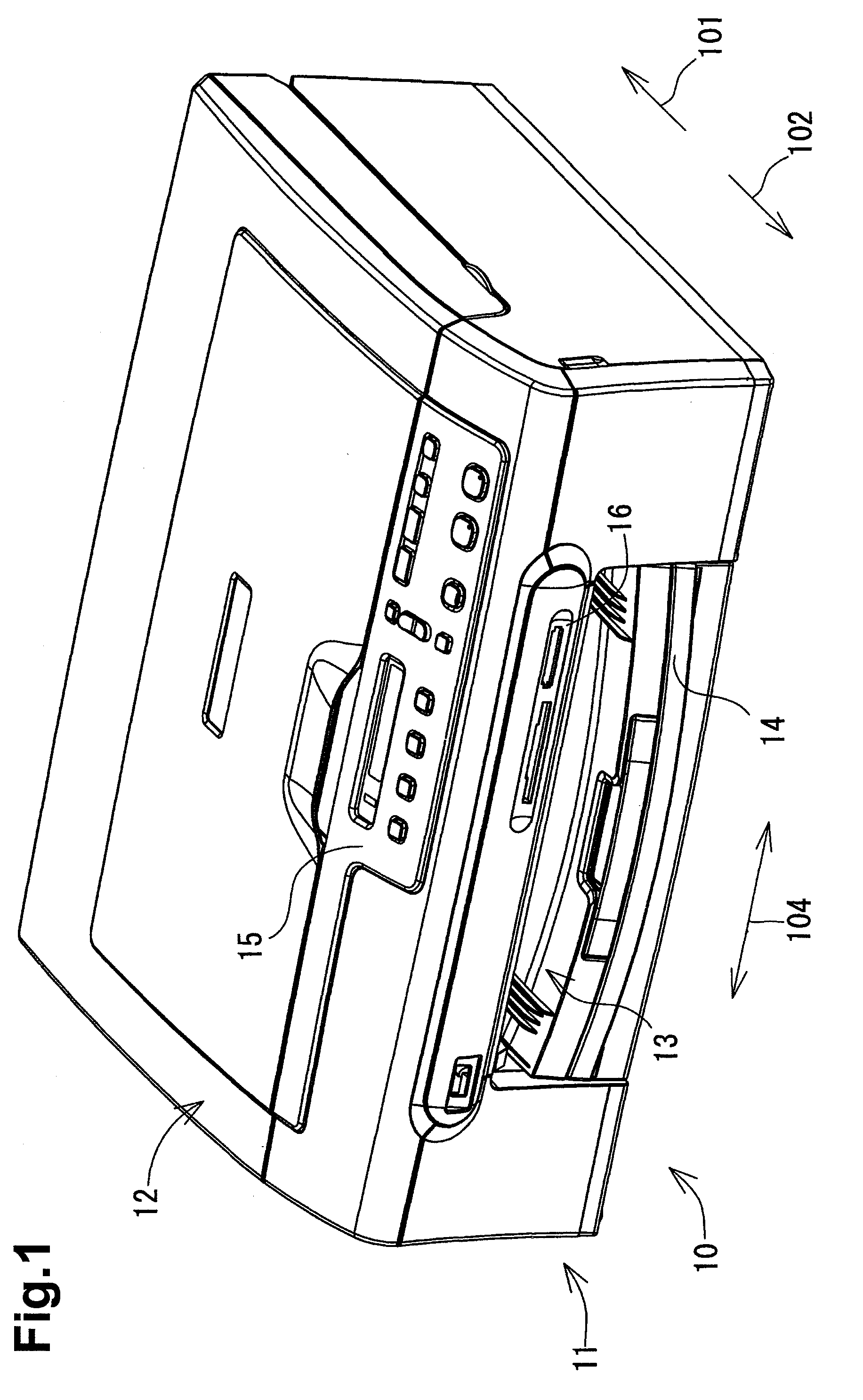
[0022]An image recording apparatus, e.g., a multi-function device 10, may comprise a printer 11 and a scanner 12, and may perform one or more functions, e.g., printing, copying, scanning, facsimile functions, or any combination thereof.

[0023]The printer 11 of the multi-function device 10 may be connected to an external device, e.g., a computer and a digital camera, and may be configured to record an image, e.g., text or the like, on a sheet of recording medium based on image data transmitted form the external device. Various storage media, e.g. card-type memories, may be inserted into the multi-function device 10, and the printer 11 may record an image on a sheet based on image data stored in a storage medium.

[0024]The multi-function device 10 has a substantially box shape, and has a width and a depth which are greater than a h...


PUM


Abstract

A sheet storing device includes a container including a first holding surface configured to hold a first sheet thereon, and a tray positioned at an upper side of the container. The tray includes a second holding surface configured to hold a second sheet thereon. The tray is configured to selectively move between a first position and a second position downstream from the first position in a first direction. The sheet storing device further includes a positioning unit configured to selectively position the tray in one of the first position and the second position, and a linking unit configured to link the tray to the container and to pivot about a particular pivot axis which extends in a second direction perpendicular to the first direction and parallel to the first holding surface of the container. The linking unit pivots to selectively move the tray between the first position and the second position.

Description

CROSS REFERENCE TO RELATED APPLICATION[0001]The present application claims priority from Japanese Patent Application No. 2008-332166, which was filed on Dec. 26, 2008, the disclosure of which is incorporated herein by reference in its entirety.BACKGROUND OF THE INVENTION[0002]1. Field of the Invention[0003]The invention relates to a sheet storing device that comprises a container for storing a first sheet and a tray for storing a second sheet. The invention also relates to an image recording apparatus that comprises such a sheet storing device and is configured to selectively feed a first sheet and a second sheet from the sheet storing device and to record an image on the fed sheet.[0004]2. Description of Related Art[0005]A known printer, e.g., an inkjet printer or a laser printer, for recording an image on a sheet of recording medium comprises a sheet storing device, e.g., a sheet cassette. The sheet storing device is configured to store sheets of a predetermined standard size. The...

Claims


Application Information

Patent Timeline
IPC IPC(8): B65H1/08B65H1/00
CPCB65H1/266B65H2402/342B65H2402/46B65H2405/332B65H2801/06B65H2402/30
Inventor WAKAKUSA, KEISUKE
Owner BROTHER KOGYO KK
Why Eureka
Eureka Blog
Learn More