
Subject tracking computer program product, subject tracking device and camera

a computer program and subject tracking technology, applied in the field of subject tracking computer program products, subject tracking devices and cameras, can solve the problems of unstable template matching, affecting the stability of template matching, and the significant change of template images, so as to achieve stable template matching

Active Publication Date: 2010-07-01
NIKON CORP
View PDF11 Cites 41 Cited by
  • Summary
  • Abstract
  • Description
  • Claims
  • Application Information

AI Technical Summary

Benefits of technology

[0017]The present invention enables stable template matching even when the subject moves along the optical axis of the camera.

Problems solved by technology

However, there is an issue to be addressed in the object tracking device in the related art in that since the plurality of template images are updated each time the matching processing is executed in correspondence to the input image in a given frame, template images will change considerably, making it rather difficult to assure stable template matching processing.
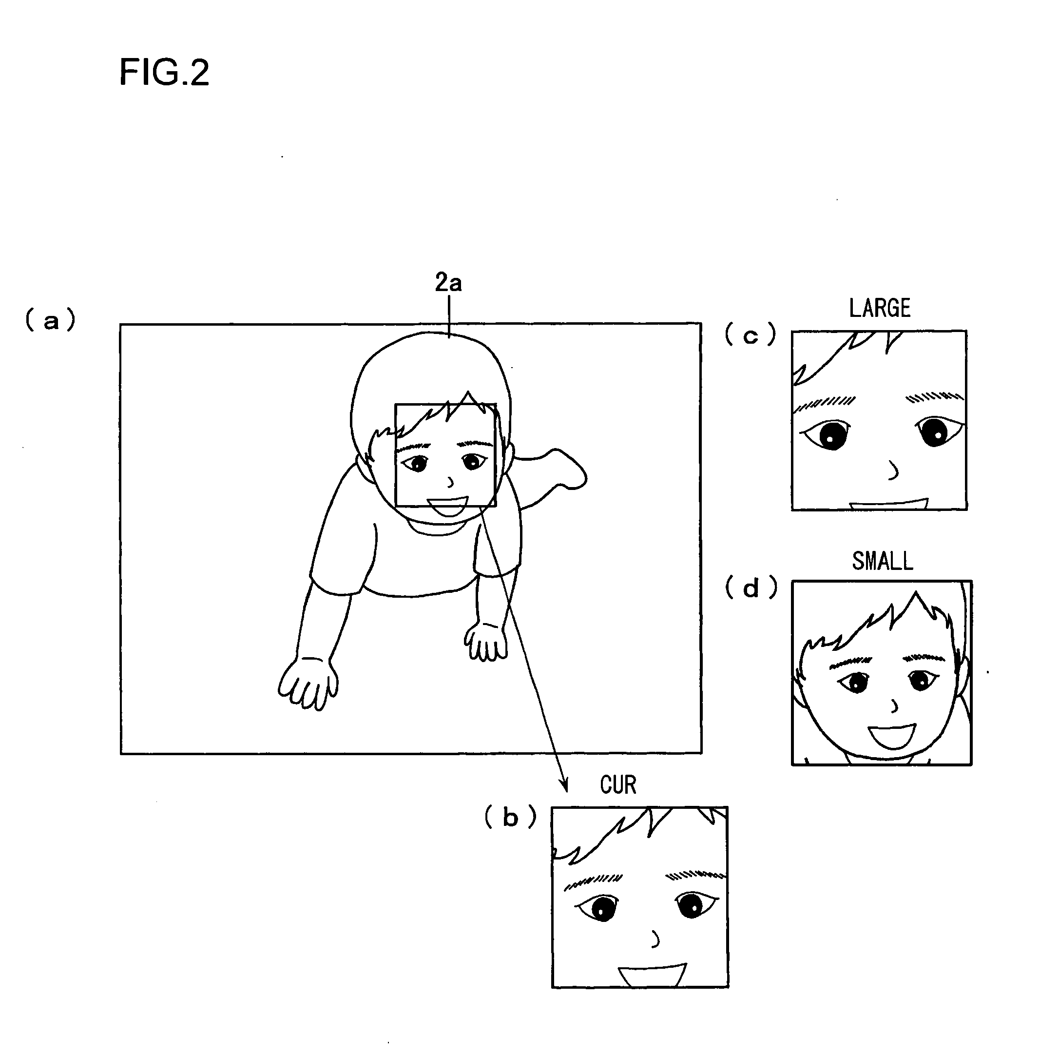
This issue may become particularly challenging in applications in which the subject racking device is adopted in a camera, since the size of a photographic subject moving along the optical axis of the camera (closer to or further away from the camera) will change and lead to instability in template matching.

Method used


Image

  • Subject tracking computer program product, subject tracking device and camera
  • Subject tracking computer program product, subject tracking device and camera
  • Subject tracking computer program product, subject tracking device and camera

Examples


first embodiment

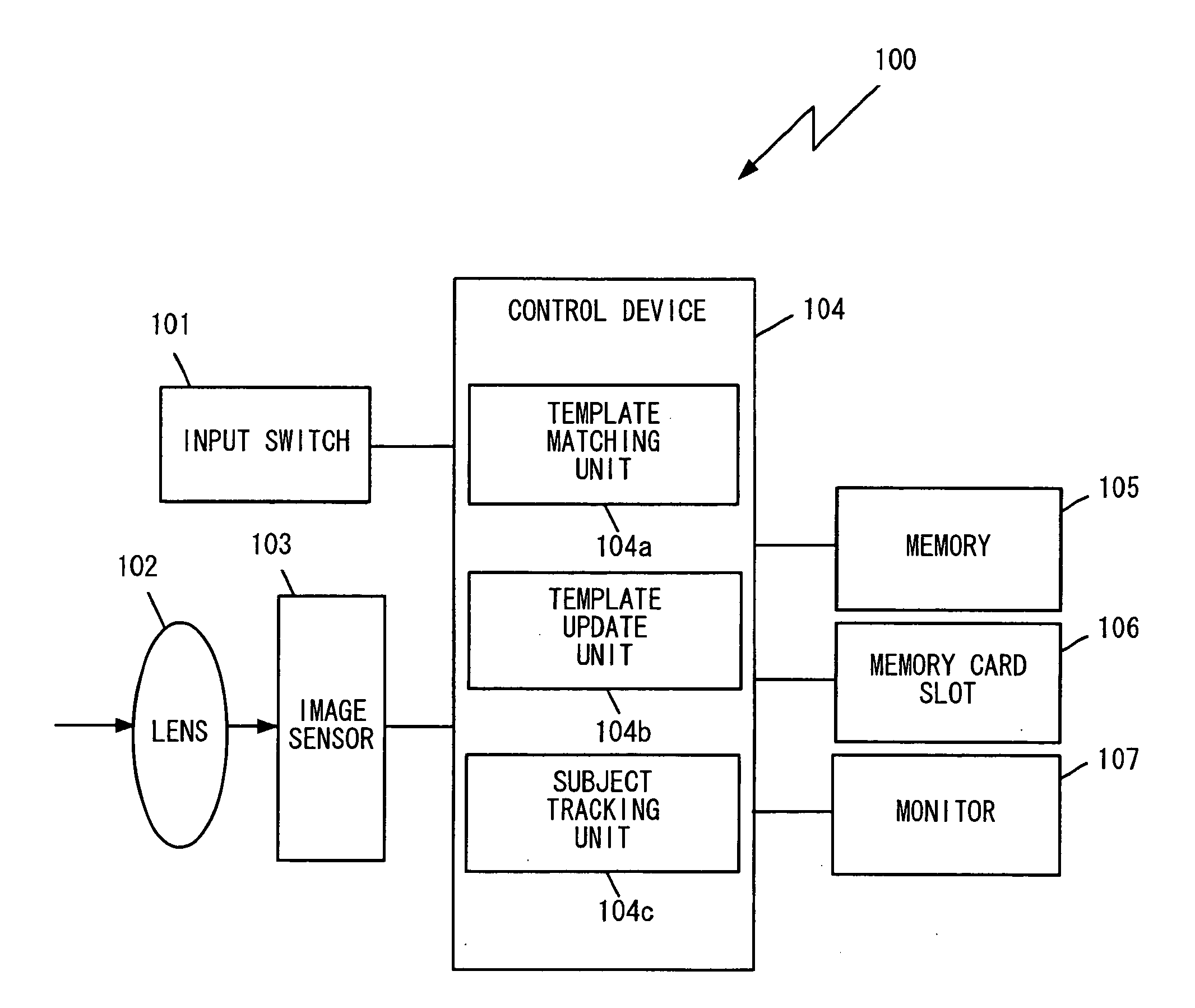
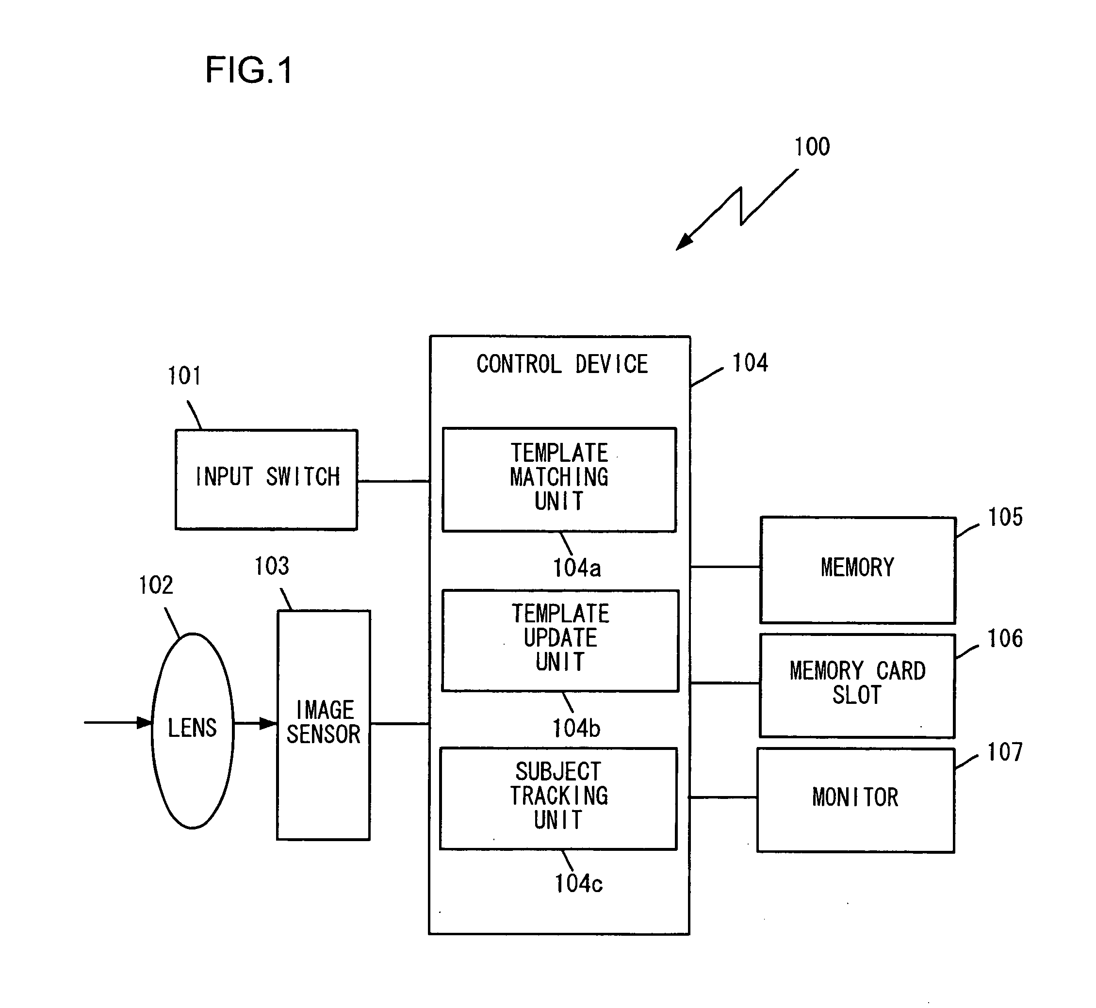
[0025]FIG. 1 is a block diagram showing the structure of the subject tracking device achieved as a camera in the first embodiment of the present invention. The camera 100 comprises an input switch 101, a lens 102, an image sensor 103, a control device 104, a memory 105, a memory card slot 106 and a monitor 107.

[0026]The input switch 101 includes various input members operated by the user. The input members included in the input switch 101 may be, for instance, a shutter release switch and various operation buttons via which the digital camera 100 is operated.

[0027]While the lens 102 is constituted with a plurality of optical lens groups, the plurality of optical lens groups are represented by a single lens in FIG. 1. The image sensor 103, constituted with, for instance, a CCD or a CMOS, obtains an image by capturing a subject image formed via the lens 102 and outputs image data expressing the captured image to the control device 104. It is to be noted that the image sensor 103 in th...

second embodiment

[0064]In the first embodiment described above, three templates, i.e., the Cur template, the Large template and the Small template, are used in template matching so as to ensure that highly accurate subject tracking is executed even as the subject moves along the optical axis of the camera 100 and the image area occupied by the subject changes from one target image to another. In the second embodiment, a plurality of template images obtained by photographing the tracking target subject at different time points are used in addition to the three template images described earlier. It is to be noted that since the block diagram in FIG. 1, in reference to which the first embodiment has been described, also applies to the second embodiment, a repeated explanation is not provided.

[0065]Assuming that the movement of the infant in the target image 5a in FIG. 5 is to be tracked from frame to frame, three images 5e˜5g of the subject, i.e., the infant, photographed at various time points (time-l...


PUM


Abstract

A computer performs a template-matching step of template-matching an input image with a plurality of template images with different magnifications by a program stored in an object racking computer program product, selecting the template image with the highest similarity to an image in a predetermined region of the input image among the plurality of template images and extracting the predetermined region of the input image as a matched region, a determination step of determining whether or not the matching results of the template-matching step satisfy update conditions for updating the plurality of template images, and an updating step of updating at least one of the plurality of template images when the update conditions are determined to be satisfied by the determination step.

Description

TECHNICAL FIELD[0001]The present invention relates to a subject tracking computer program product containing a subject tracking program based upon which a photographic subject is tracked from one image to another through a plurality of input images, a subject tracking device and a camera.BACKGROUND ART[0002]There is an object tracking device known in the related art. The object tracking device executes matching processing by comparing the input image in each frame with a plurality of template images obtained at different times. It then designates the area of the input image achieving the highest level of match as a template matching position and designates the image at the template matching position as a new template image for an update so as to accurately track the tracking target object, which may change its shape (see patent reference 1).[0003]Patent reference 1: Japanese Laid-Open Patent Publication No. 2001-60269DISCLOSURE OF THE INVENTIONProblems to Be Solved by the Invention[...

Claims


Application Information

Patent Timeline
IPC IPC(8): H04N5/225G06K9/00G06V10/772
CPCG06K9/6203G06K9/6255G06T2207/10016G06T2207/30201G06T2207/30241G06T7/248G06V10/7515G06V10/772G06F18/28
Inventor ABE
Owner NIKON CORP
Learn More