Luminaire with Adjustable Light Source

a technology of adjustable light source and light source, which is applied in the direction of lighting and heating apparatus, coupling device connection, lighting support device, etc., can solve the problem of not being able to meet the custom illumination pattern easily

Inactive Publication Date: 2010-07-01
WILKINSON DEAN ANDREW +1
View PDF4 Cites 21 Cited by
  • Summary
  • Abstract
  • Description
  • Claims
  • Application Information

AI Technical Summary

Benefits of technology

[0010]Still other embodiments of the luminaire with adjustable light source can use a number of different light sources on a mix and match basis. For example light sources can vary in light emission pattern from spot to flood or in intensity of the light. Depending upon the required lighting pattern a luminaire can employ a number of different types of light sources with various light emission patterns and emission intensities to achieve the required illumination pattern. This approach allows designers to achieve required light patterns with reduced wattage (reduced energy consumption).
[0012]In still other embodiments the luminaire with an adjustable light source uses a baffle plate with tab-pairs formed in the material of the baffle plate. The tabs of the tab-pairs are bendable out of the surface of the baffle plate, and define a respective axis between them. Each of the light sources, rotatably attaches between one of the tab-pairs and rotates about the axis of the tab-pair. One or both of the tabs of the tab-pairs can be slotted so that the respective axis is adjustable between the tab-pairs. This allows further versatility in the aiming of each light source. As discussed earlier, the baffle plate with tab-pairs can also benefit from light sources that vary in pattern and intensity as well as thermal contacts and vents to conduct heat away from the light source.

Problems solved by technology

More problematic are cases where local geography requires customized illumination patterns not easily met by standardized luminaire types.

Method used


Image

  • Luminaire with Adjustable Light Source
  • Luminaire with Adjustable Light Source
  • Luminaire with Adjustable Light Source

Examples


Embodiment Construction

[0026]In the following description, reference is made to the accompanying drawings that form a part thereof, and in which is shown by way of illustration specific exemplary embodiments in which the invention may be practiced. These embodiments are described in sufficient detail to enable those skilled in the art to practice the invention, and it is to be understood that modification to the various disclosed embodiments may be made and other embodiments may be utilized, without departing from the spirit and scope of the present invention. The following detailed description is therefore, not to be taken in a limiting sense.

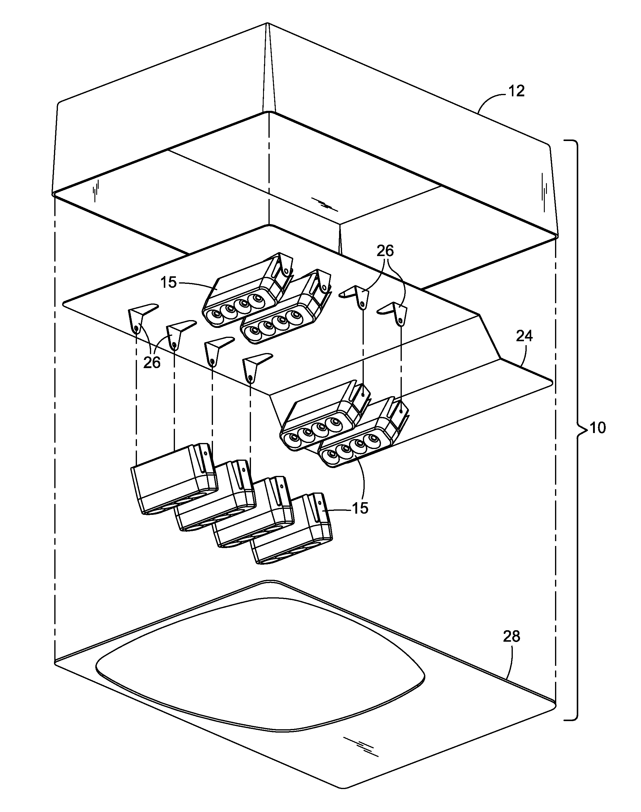
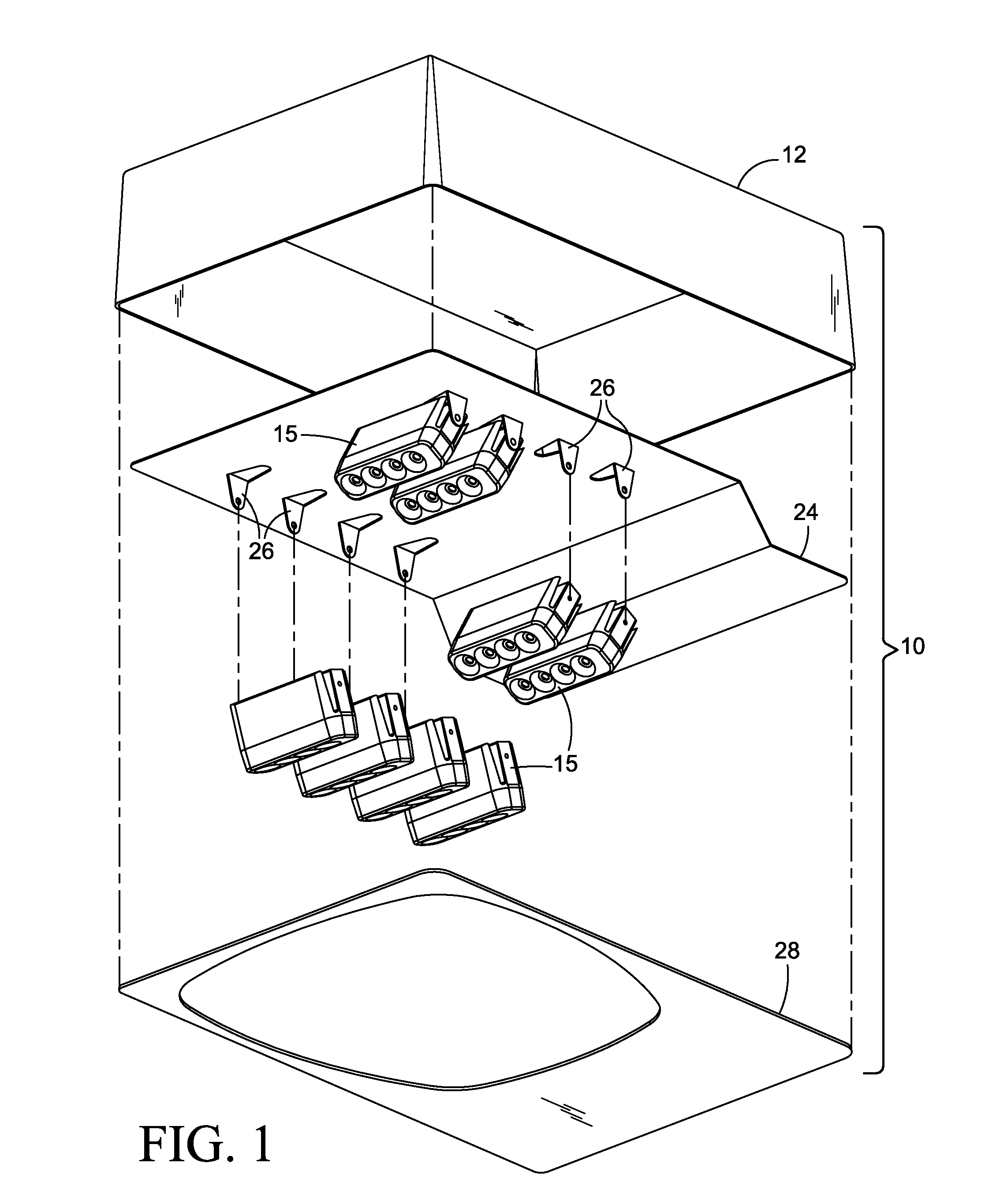
[0027]FIG. 1 shows an exploded view of one embodiment of a luminaire 10. The luminaire has a box 12 which acts as a cover for the luminaire components as well as a chassis for holding the components. Together, the box 12 and cover 28 form the luminaire body. In many cases a pole (not shown) elevates the luminaire 10 above a street or sidewalk to provide illumination...


PUM


Abstract

Light sources in a luminaire attach to the luminaire by one or more tabs. Up to three axis of rotation are possible. Bendable tabs enable a first axis of rotation of the light source. Light sources are rotatable about a mounting point to the tab providing a second axis of rotation. Some tabs are twistable about a third axis of rotation. Some tabs also conduct heat away from the light source. Tabs can also be formed in a baffle plate for new luminaires or for the retrofit of existing luminaires. Multiple types of light sources can be combined to provide luminaires with custom light patterns and intensities.

Description

CROSS REFERENCE TO RELATED APPLICATIONS [0001]This application claims the benefit of the provisional application entitled “Luminaire with Adjustable Light Source” by Dean Wilkinson and Nathan Calvin, Ser. No. 61 / 141,654 filed Dec. 30, 2008, and is hereby incorporated by reference in its entirety.FEDERALLY SPONSORED RESEARCH OR DEVELOPMENT [0002]Not applicable.JOINT RESEARCH AGREEMENT [0003]Not applicableSEQUENCE LISTING [0004]Not applicableFIELD OF THE INVENTION [0005]The present invention relates to the field of lighting fixtures also called luminaires, and in particular to lighting fixtures with adjustable illumination patterns.BACKGROUND OF THE INVENTION[0006]Currently for outdoor lighting, numerous types of luminaires exist. They differ not only in style but especially with respect to the illumination pattern. For example, sidewalks require long, narrow illumination patterns while traffic intersections require broader, wide area illumination patterns. Within the lighting industr...

Claims


Application Information

Patent Timeline
Patent Type & Authority Applications(United States)
IPC IPC(8): F21V9/00F21V19/02F21S4/00
CPCF21S2/005F21V17/007F21V21/30F21V29/004F21W2131/10F21W2131/103F21Y2103/10F21Y2115/10F21V29/70
Inventor WILKINSON, DEAN ANDREWCALVIN, NATHAN HOWARD
Owner WILKINSON DEAN ANDREW
Why Eureka
Try Eureka