

Smart motor driving air cylinder device
A technology for driving cylinders and cylinder devices, used in power control mechanisms, door/window fittings, buildings, etc., can solve the problems of poor stability, increased bearing capacity, and high noise of steel springs, prevent cylinder liner from rotating, reduce the overall Length, effect of reducing motor wattage
Active Publication Date: 2017-09-08
宁波拓尔精工机械有限公司
View PDF10 Cites 3 Cited by
- Summary
- Abstract
- Description
- Claims
- Application Information
AI Technical Summary
Problems solved by technology
[0005] The driving device of the above-mentioned type of electric tailgate is mainly supported by steel springs, the driving force is generated by the motor, and the expansion and contraction is realized through the screw rod. The steel spring has the following disadvantages: first, the steel spring has poor stability and is easy to break. There are potential safety hazards; secondly, the weight of the tailgate of the car is different, and it needs to be adapted to drive devices of different specifications, and the torque of the steel spring cannot be adjusted; thirdly, the steel spring is easy to rub against the steel pipe wall during reciprocating motion to generate noise; finally , the steel spring must be made relatively thick, and the whole is relatively bulky, causing the bearing capacity of both ends of the load to double when the tailgate is closed, and the strength requirements for the fixing devices at both ends are increased
But the technical solution of this application also has the following deficiencies: first, the noise is relatively large, and the noise mainly comes from the rotation of the motor itself and the multi-start screw and the multi-start screw sleeve; second, the overall structure is still relatively bloated, and the internal air pressure is not fully utilized. It cannot be made small; third, the overall length is still long, and the application is relatively limited; fourth, the hollow screw structure requires high machining accuracy, and there are certain difficulties in process realization
Method used
View moreImage
Smart ImageViewing Examples

Examples
Embodiment 2
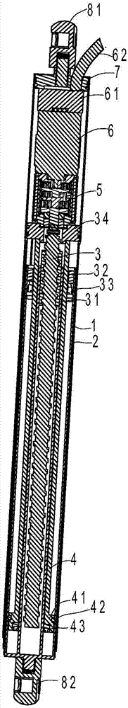
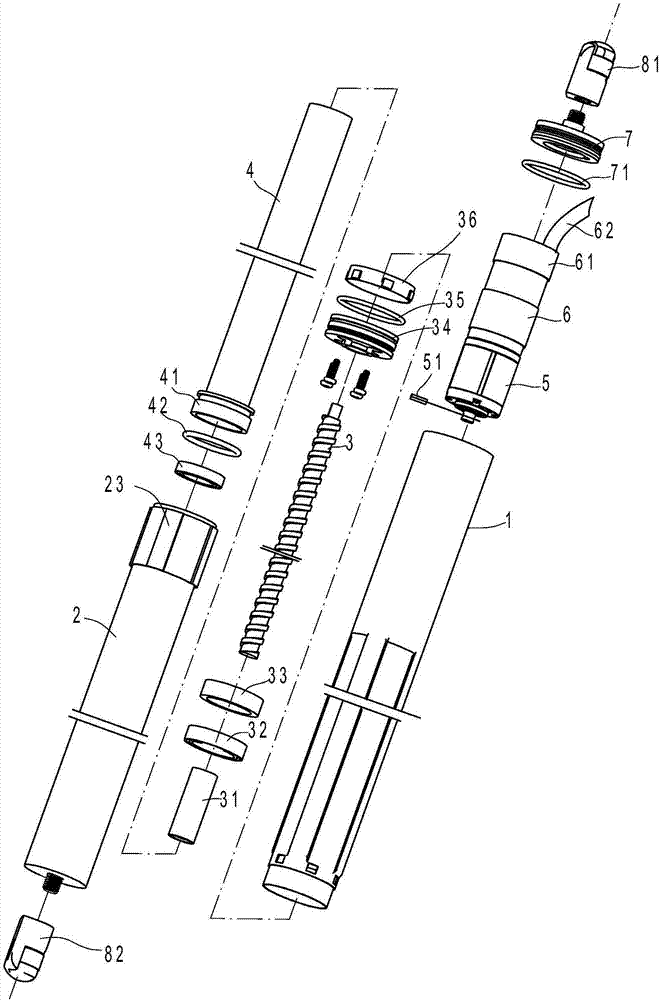
[0050] Embodiment 2, the piston 41 in this embodiment is provided with a through hole 411, and the through hole 411 communicates the air chambers at the front and rear ends of the piston 41, so that when the piston rod 4 is in motion and a large pressure difference is generated, the compressed gas can flow through the through hole. The flow in the hole ensures balance, so that the piston 41 is kept basically stable under the force of the compressed gas, thereby achieving better performance than the steel spring. Refer to Example 1 for other structures.
Login to View More PUM
 Abstract
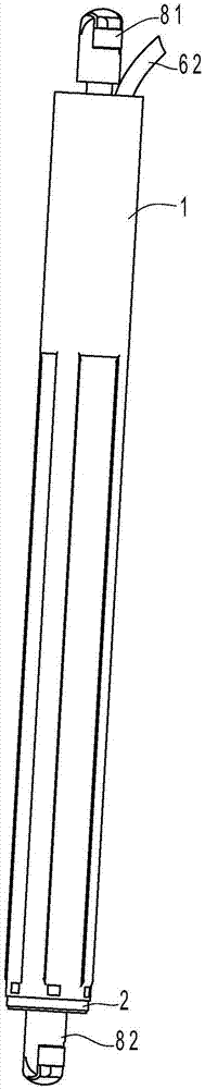
A smart motor driving air cylinder device is characterized in that the smart motor driving air cylinder device comprises an outer pipe, a direct current motor, a reducer, a cylinder sleeve, a piston rod, a screw sleeve, a multi-head screw rod and a positioning sleeve. The cylinder sleeve can move back and forth relative to the outer pipe and comprises a small cylinder sleeve and a big cylinder sleeve, the small cylinder sleeve is located in the middle of the big cylinder sleeve, and an annular area is formed between the outer wall of the small cylinder sleeve and the inner wall of the big cylinder sleeve; the piston rod is hollow to form an inner cavity and a piston is formed at the front end of the piston rod, the small cylinder sleeve is sleeved with the piston rod, and the piston is located in the annular area between the outer wall of the small cylinder sleeve and the inner wall of the big cylinder sleeve; and one end of the multi-head screw rod is connected with the output end of the reducer, and the other end of the multi-head screw rod extends into the small cylinder sleeve and is connected and matched with the screw sleeve. Compared with the prior art, the smart motor driving air cylinder device has the advantages that the structure is compact, portability is achieved and the noise is low.
Description
technical field [0001] The invention relates to an electric driving device, in particular to a driving device applied to a tailgate of an automobile. Background technique [0002] At present, there are two main types of car tailgates. The first is the manual tailgate, which uses gas springs to realize manual opening and closing. This type of structure is mainly used in low-end and mid-end cars; the second is the electric tailgate, which is driven by a motor to realize the tailgate. The automatic lift is convenient and quick to operate, and at the same time, it solves the problem that most female passengers struggle to open the tailgate due to their small strength. [0003] There are many kinds of driving devices for the electric tailgate, such as the Chinese invention patent application publication "Electric Gas Spring" (the application publication number is CN103410906A) whose application number is 201310343833.3. This application drives the piston rod to move back and fort...
Claims
Login to View More Application Information
Patent Timeline
 Patent Type & AuthorityApplications(China)
IPC IPC(8): E05F15/53
CPCE05F15/00E05F15/53E05Y2201/454E05Y2900/532
Inventor潘微杰
Owner宁波拓尔精工机械有限公司