
Model-based method and system for image segmentation and modelling

Inactive Publication Date: 2010-07-01
AGENCY FOR SCI TECH & RES
View PDF8 Cites 5 Cited by
  • Summary
  • Abstract
  • Description
  • Claims
  • Application Information

AI Technical Summary

Benefits of technology

[0015]The convergence condition used for termination of the iteration may be the minimization of an energy function related to the force. Thus, the embodiments of the invention may have the convergence advantages of PDMs.
[0017]The narrowband may include two sets of locations (pixels in a 2D space or voxels in a 3D space): first locations at the boundary of the model (level set) and second locations in a neighbourhood of the boundary (“narrowband region”). The force at the first locations is calculated using the medical data, and the force at the second locations is calculated using the calculated force at the first locations. Specifically, around each of the second locations a neighbourhood may be defined, and the force at the second locations can be found by reference to the force at those first locations which are within the neighbourhood. It has been found that this use of neighbourhoods reduces (or even avoids) the leakage problem (in which the object may wrongly grow to other regions of the space).

Problems solved by technology

When the topology preserving transformations are required for a deformable model, self-intersections can become a problem.
These constraints are particularly important when local features of the model and image are liable to deform the model in unexpected ways.
The deformation procedures in PDMs have an explicit stop condition which is the minimization of some kinds of energy function, whereas in GDMs, the procedure usually stops when the certain number of iterations reaches a predetermined maximum, but no simple and fast methods are available to automatically estimate a suitable maximum number of iterations.

Method used


Image

  • Model-based method and system for image segmentation and modelling
  • Model-based method and system for image segmentation and modelling
  • Model-based method and system for image segmentation and modelling

Examples


Embodiment Construction

[0031]1. Overview of Embodiment

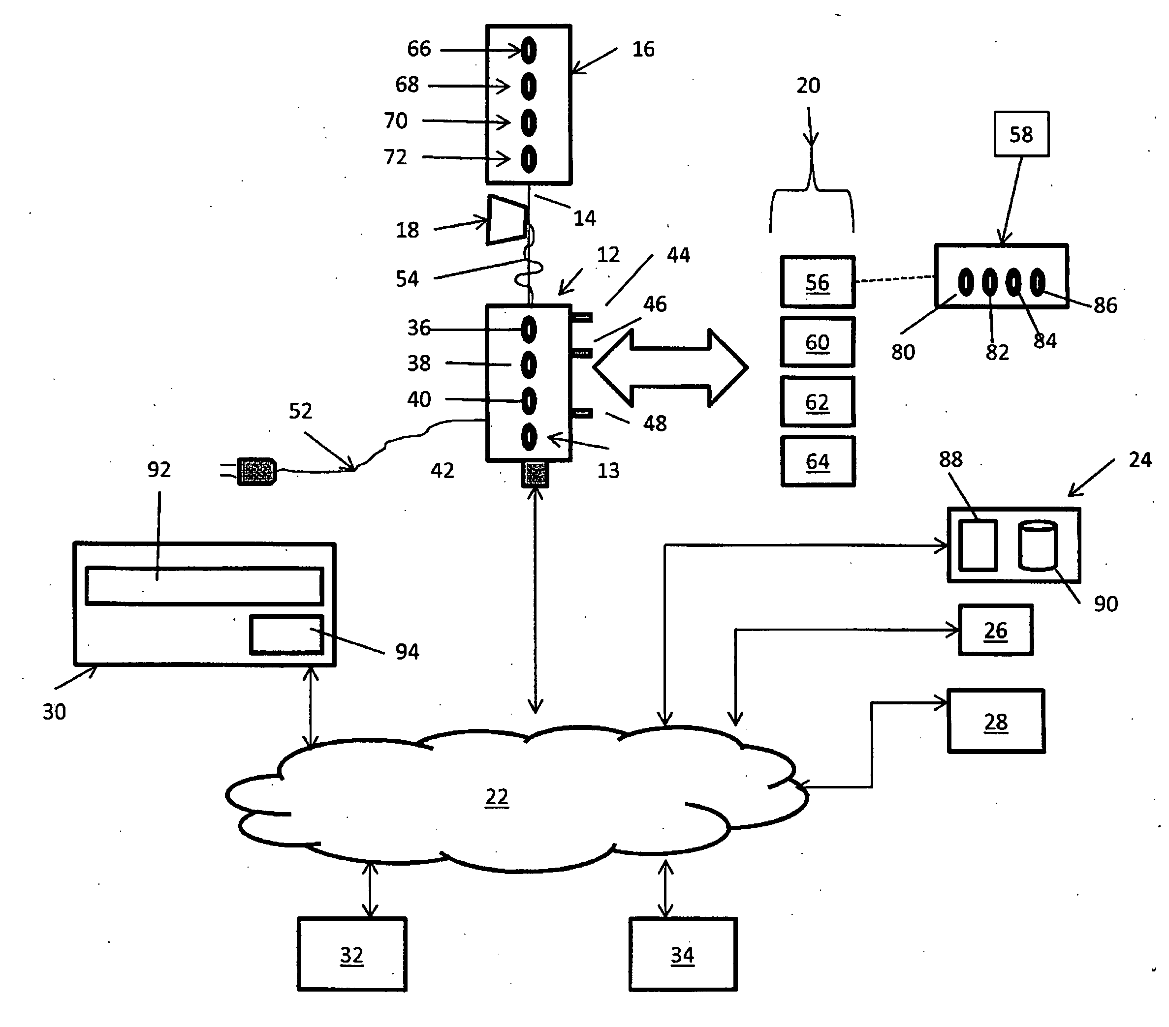
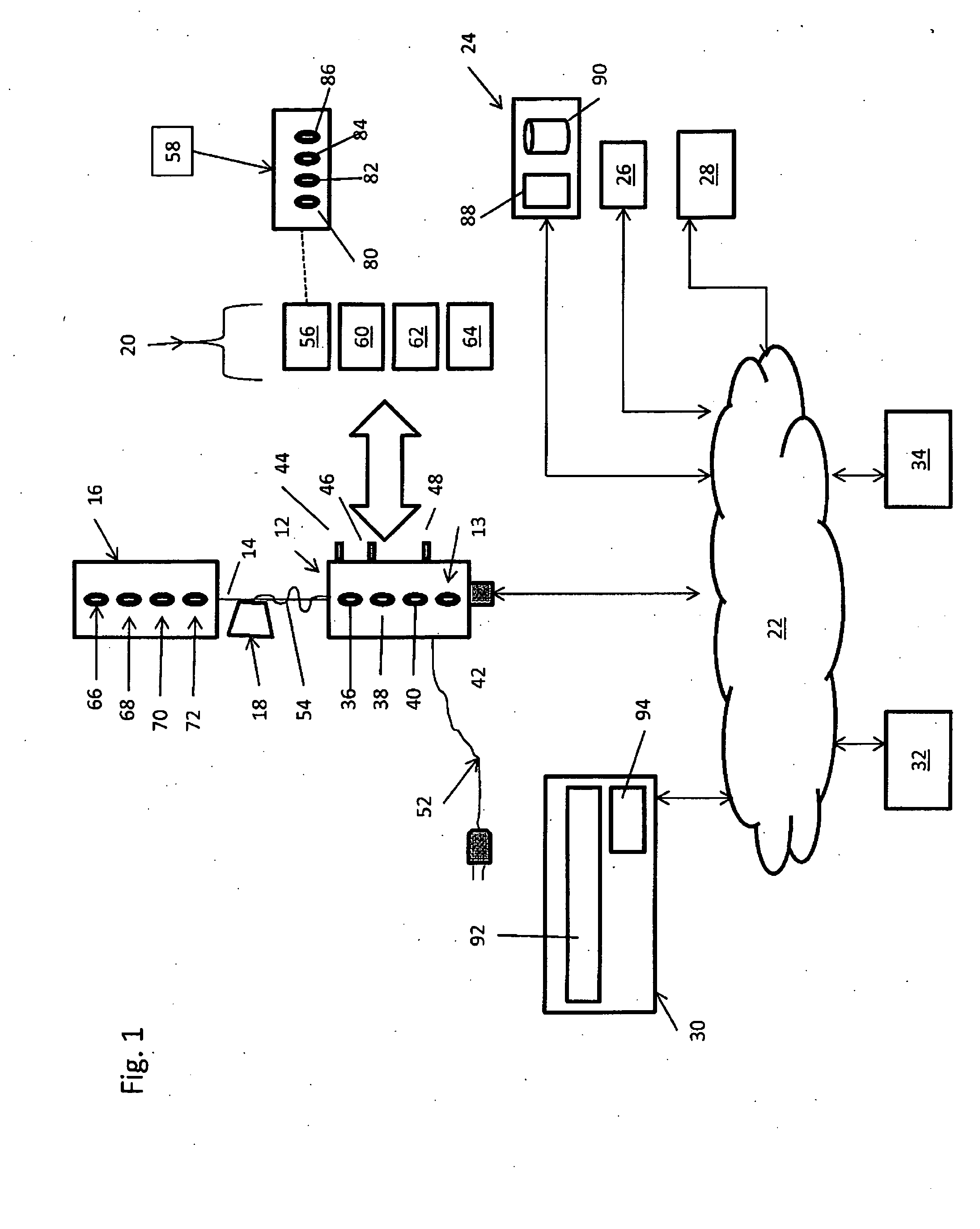
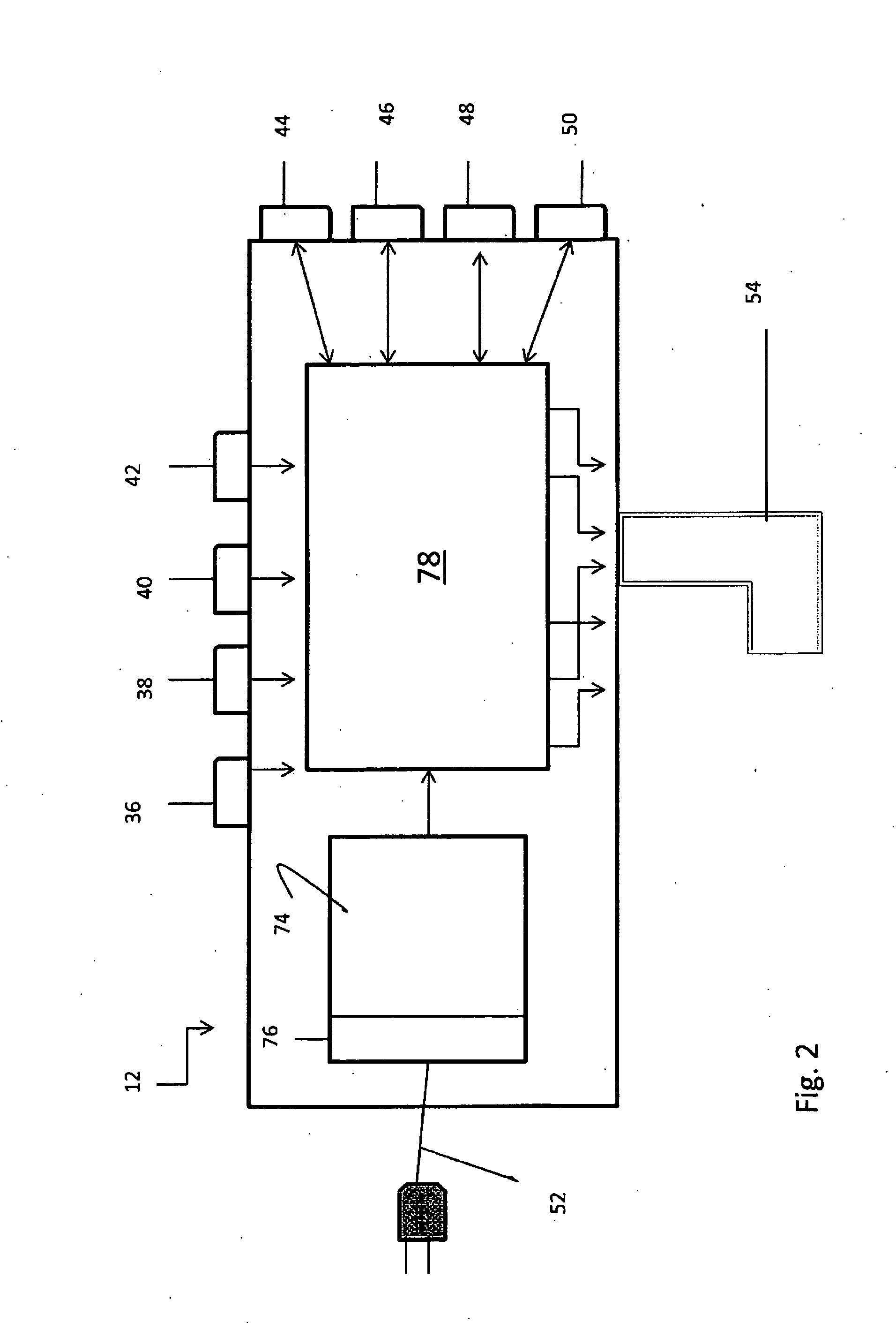
[0032]An embodiment of the invention will now be described with reference to FIGS. 1 to 3. This embodiment is used for the segmentation of a medical dataset which is a set of intensity values, such as an MR image. The intensity values are associated with respective points in a two- or three-dimensional space. The segmentation identifies an object within the image. Specific examples are given of the use of the embodiment for segmenting orbital muscles within MR images, but application of the embodiment to other segmentations tasks is straightforward.

[0033]The embodiment employs an initial model which is defined in the space of the image. If the space of the image is 2D, the initial model is a contour represented polygon, or, if the space of the image is 3D, the model is a surface represented by triangle meshes. The contour or surface forms one or more closed inside regions which indicate object itself. The model is chosen manually based on the prior-kno...


PUM


Abstract

A method is proposed for segmenting a 2- or 3-D space, spanned by a set of medical data comprising intensity values at locations within the space, to estimate the position of an object of medical significance. The method using a level set function having a level set which provides a model of boundary of the object. The level set function is iteratively updated by a force defined based on the medical data. For computational efficiency, only the force in the narrowband of the model boundary needs to be calculated. Minimisation of an energy function, related to the force, provides a termination condition for the iteration. High level knowledge can be incorporated in several ways, such as by an explicit force term which takes over from the force based on the medical data when prior knowledge of the object is about to be violated by the model.

Description

FIELD OF THE INVENTION[0001]The present invention relates to a method and system for segmenting a space spanned by a set of medical data, such as a 2- or 3-dimensional MRI image of at least part of a brain or other structure consisting of a set of intensity values at corresponding locations in the space. The segmentation produces a model of an object having medical significance, that is an estimate of the portion of the space occupied by the object.BACKGROUND OF THE INVENTION[0002]Since their introduction by Kass et al. (Kass 1988), a variety of deformable models have been proposed and used in a numerous areas such as image segmentation, shape modeling, and object tracking. Existing deformable models can be classified as either parametric deformable models (PDMs) (Kass, 1988; Cohen, 1991; Xu, 1998; McInery, 1996; Cottes, 1991, 2001; Shen, 2001; Liu, 2005) or geometric deformable models (GDMs) (Malladi, 1995; Caselles, 1997; Yezzi, 1997; Sethian, 1999; Han, 2003) according to their r...

Claims


Application Information

Patent Timeline
IPC IPC(8): G06K9/62
CPCG06K9/6207G06K2209/05G06T2207/10088G06T2207/20161G06T2207/30016G06T7/12G06T7/149G06V10/755G06V2201/03
Inventor LIU, JIMIN
Owner AGENCY FOR SCI TECH & RES
Learn More