Force sensing oar

a force sensing and oar technology, applied in the field of oars, can solve the problems of weaker rowing stroke, inexperienced rowers may be unsure how to make the stroke more powerful, and inexperienced rowers may be reluctant to change their form, etc., to achieve cost-effective and manageable effects

Inactive Publication Date: 2010-07-01
LUECKER MICHAEL C +1
View PDF2 Cites 22 Cited by
  • Summary
  • Abstract
  • Description
  • Claims
  • Application Information

AI Technical Summary

Benefits of technology

[0010]The present invention is directed to a system and method for providing performance feedback from a rowing oar, and in a preferred configuration, an oar equipped with a processor, a power supply, and deflection and temperature sensors is use

Problems solved by technology

For example, inexperienced rowers commonly start out rowing in a manner that feels natural and may mistakenly believe a rowing stroke is powerful when in fact the rowing form is incorrect.
Incorrect rowing form results in a weaker rowing stroke.
Another challenge is that when a rowing coach instructs inexperienced rowers to correct their form, the inexperienced rowers may be unsure how to make the stroke more powerful using the new and unfamiliar rowing form.
As a result, inexperienced rowers may be reluctant to cha

Method used


Image

  • Force sensing oar
  • Force sensing oar
  • Force sensing oar

Examples


Embodiment Construction

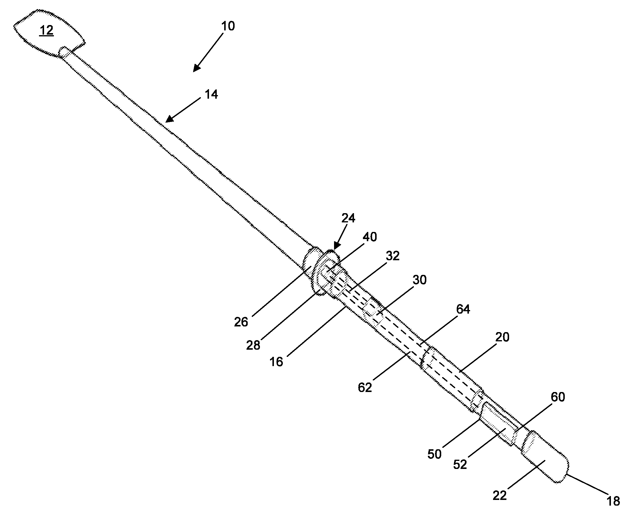
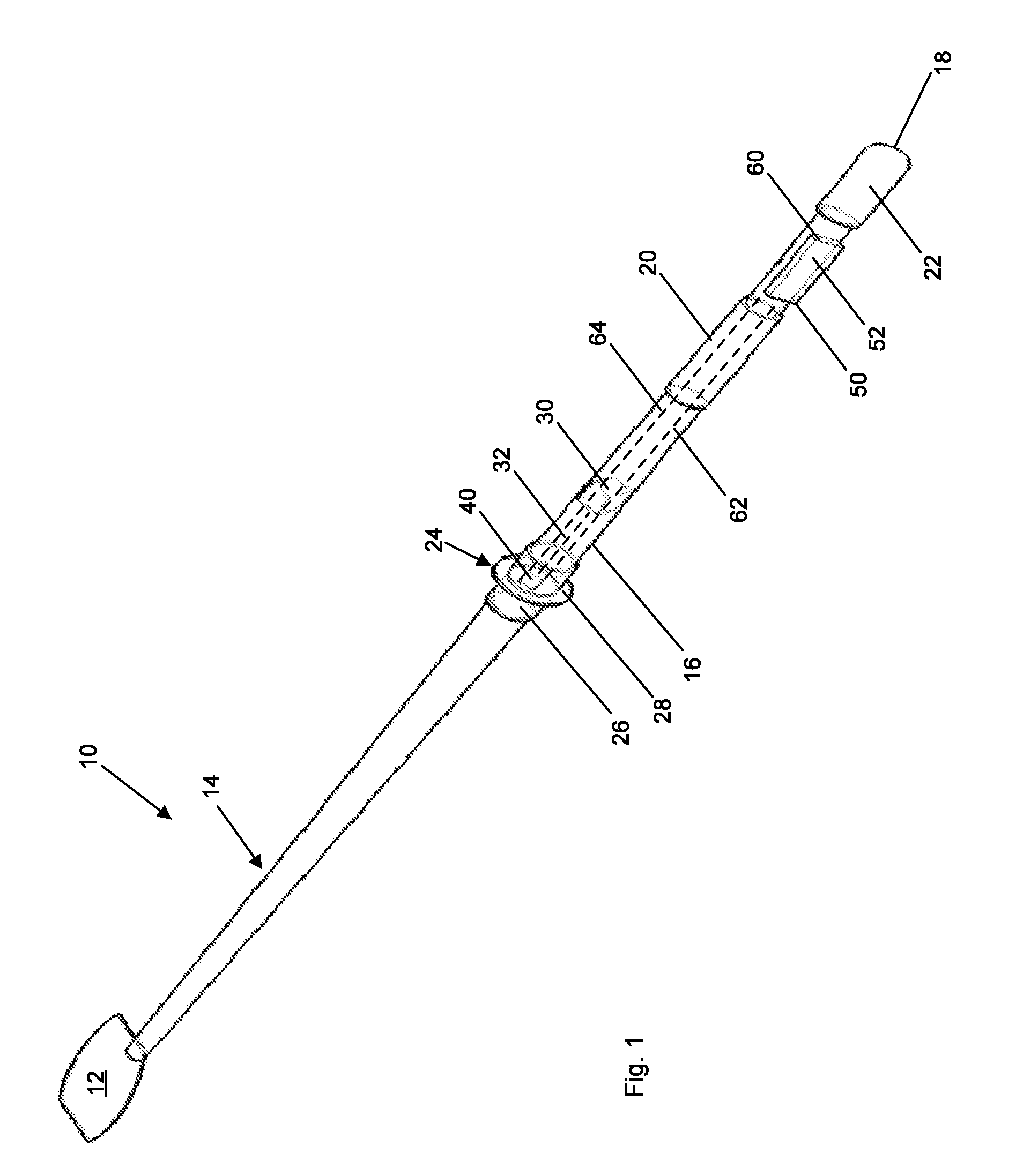
[0017]This disclosure describes a self-contained oar device that does not require boat modifications, vulnerable cabling, frequent calibration, or additional bulky equipment. While the following discussion references a preferred embodiment having a specific sensor placement and using a specific processor and display configuration, the invention is not limited to the particular details discussed. The invention is defined by claims in this non-provisional application.

[0018]FIG. 1 shows sweep-rowing oar 10. Alternately oar 10 may be another suitable oar such as, but not limited to, a sculling oar. Oar 10 is either a port or starboard sweep oar capable of being used by any rower in an 8+, 4+, or pair crew shells. Oar 10 is designed for use by competitive high school rowing teams, club organizations, collegiate, and Olympic organizations. With respect to FIG. 1, in a preferred embodiment oar 10 has cleaver oar blade 12 attached to the end of loom 14 of hollow oar shaft 16. Oar shaft 16 i...


PUM


Abstract

A system for determining the magnitude of force applied to an oar by a rower as the oar is pulled through water includes a deflection sensor and a temperature sensor mounted on an oar shaft to determine deflection and temperature of a portion of the oar shaft during rowing. A processor connected to the deflection sensor and the temperature sensor receives signals indicative of deflection and temperature of the oar shaft and derives a force applied to an oar blade based on the deflection and temperature signals.

Description

RELATED APPLICATIONS[0001]This application claims priority under 35 U.S.C. §119(e) to U.S. Patent App. No. 61 / 203,809 titled “Precision Rowing Oar—P.R.O.” and filed on Dec. 28, 2008, which is fully incorporated by reference herein.TECHNICAL FIELD[0002]The present disclosure relates to a rowing oar, and in particular, a rowing oar for determining a magnitude of force acting on the oar blade when a rower moves the oar blade through water.BACKGROUND[0003]The present inventors have recognized that common practices for coaching rowing teams involves several aspects that coaches use to assess each individual rower's performance to determine which combination of rowers will likely row a boat the fastest. One aspect is knowing which individuals are rowing with the most force so coaches have an idea of who is moving the boat through the water most powerfully. Another aspect is tracking each individual's force output over time to pair rowers with complementary force-outputs and rowing styles ...

Claims


Application Information

Patent Timeline
IPC IPC(8): B63H16/04G01K13/00G01L1/00G06F17/00
CPCA61B5/224A63B24/0062A63B69/06A63B2220/54A63B2220/58A63B2220/72A63B2225/50B63H16/04G01K13/00
Inventor LUECKER, MICHAEL C.LINSE, MICHAEL H.
Owner LUECKER MICHAEL C
Why Eureka
Try Eureka