Methods for removing a valve from a vessel

a valve and valve body technology, applied in the field of tissue removal, can solve the problems of considerable para-valvular leak regurgitation and early mortality, limited durability of bav, and difficulty in insertion of devices, etc., and achieve the effects of increasing temperature, increasing temperature, and increasing temperatur

Active Publication Date: 2010-07-01
CVDEVICES
View PDF22 Cites 10 Cited by
  • Summary
  • Abstract
  • Description
  • Claims
  • Application Information

AI Technical Summary

Problems solved by technology

The durability of BAV is restricted.
Unsatisfactory results of balloon aortic valvuloplasty (BAV) have lead to investigation of percutaneous placement of prosthetic aortic valves.
Although percutaneous aortic valve insertion has been performed on extremely high-risk patients, considerable para-valvular leak regurgitation and early mortality have discouraged this approach.
One of the biggest problems with percutaneous or transapical aortic valve replacement is the dilatation of a calcific aortic valve prior to delivery of the stent valve device.
The consequences of irregular dilation of the aortic valve area are periprosthetic leak, calcium embolization, difficulties with device insertion and possible migration of the device.

Method used


Image

  • Methods for removing a valve from a vessel
  • Methods for removing a valve from a vessel
  • Methods for removing a valve from a vessel

Examples


Embodiment Construction

[0043]For the purposes of promoting an understanding of the principles of the present disclosure, reference will now be made to the embodiments illustrated in the drawings, and specific language will be used to describe the same. It will nevertheless be understood that no limitation of the scope of this disclosure is thereby intended.

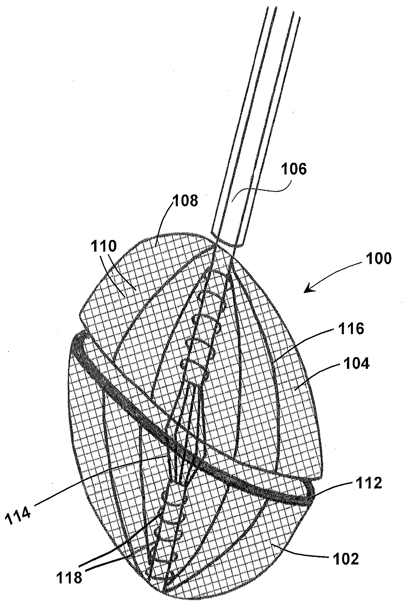
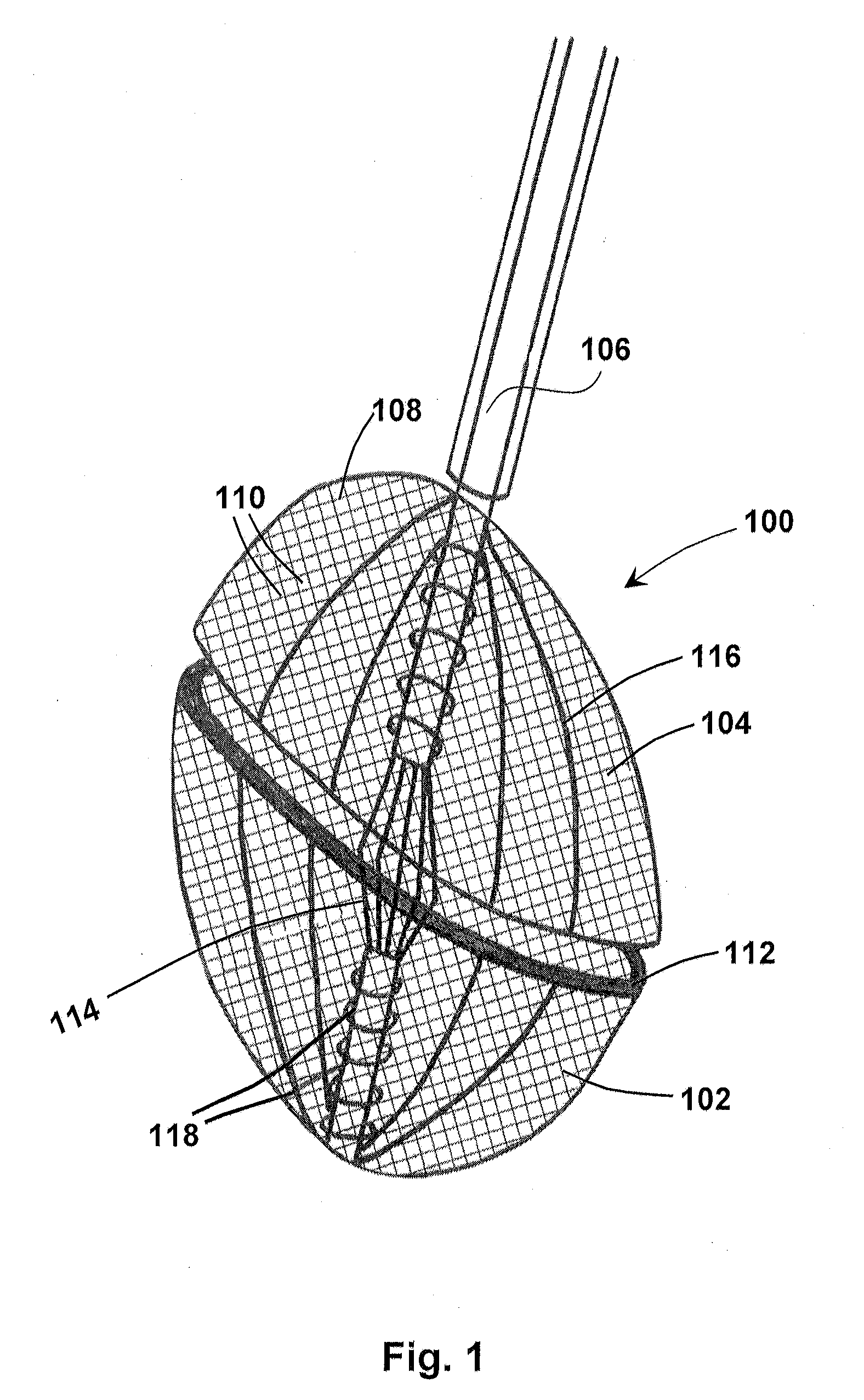
[0044]The disclosure of the present application relates generally to tissue removal, and more particularly to devices, systems, and methods for percutaneous and mini-invasive valve removal. In at least one embodiment, an umbrella device comprises two opposing umbrellas, a cauterizing mechanism, and a drill, wherein the umbrella device is operable to percutaneously engage and remove a valve.

[0045]An exemplary embodiment of an umbrella device according to the present disclosure is shown in FIG. 1. As shown in FIG. 1, umbrella device 100 comprises a first umbrella 102 and a second umbrella 104 coupled to shaft catheter 106. As shown in the exemplary embodi...


PUM


Abstract

Methods for removing a valve from a bodily vessel. In at least one method for removing a valve from a bodily vessel, the method comprises the steps of introducing an umbrella device into a vessel, positioning the umbrella device within an aperture within the valve, deploying a first umbrella of the umbrella device on a first side of the valve to engage the valve at the first side of the valve, deploying a second umbrella of the umbrella device on a second side of the valve to engage the valve at the second side of the valve, operating a mechanical drill of the umbrella device to grind the valve, collapsing the first umbrella and the second umbrella to facilitate withdrawal of the umbrella device from the vessel, and withdrawing the umbrella device from the vessel.

Description

PRIORITY[0001]This U.S. continuation patent application is related to, and claims the priority benefit of, U.S. Nonprovisional patent application Ser. No. 12 / 602,337, filed Nov. 30, 2009, which is related to, claims the priority benefit of, and is a U.S. national stage application of, International Patent Application No. PCT / US2008 / 064974, filed May 28, 2008, which is related to, and claims the priority benefit of, U.S. Provisional Patent Application Ser. No. 60 / 940,617, filed May 29, 2007. The contents of each of these applications are hereby incorporated by reference in their entirety into this disclosure.BACKGROUND[0002]The disclosure of the present application relates generally to tissue removal, and more particularly to devices, systems, and methods for percutaneous and mini-invasive valve removal.[0003]For decades, percutaneous interventional therapy has been an option for patients with pulmolic, mitral, and / or aortic valvular disease. The treatment preferred in selected patie...

Claims


Application Information

Patent Timeline
Patent Type & Authority Applications(United States)
IPC IPC(8): A61F2/06A61B17/22A61F2/24
CPCA61B17/221A61B17/320725A61B17/320758A61F2/2436A61B2017/22097A61F2/2418A61B2017/00287
Inventor KASSAB, GHASSAN S.
Owner CVDEVICES
Why Eureka
Try Eureka