Cutting device

Inactive Publication Date: 2010-07-08
STORA ENSO AB
View PDF15 Cites 3 Cited by
  • Summary
  • Abstract
  • Description
  • Claims
  • Application Information

AI Technical Summary

Benefits of technology

[0006]The purpose of this invention is to resolve these problems and produce a cutting device of the type mentioned in the introduction which is simple in design and where the sluggishness in the cylinder's piston seal does not affect the rotation of the knife pulley as well as providing an exact setting of the compressive force between the edges of the knife pulleys. The purpose of the invention is also to produce a method of the type mentioned in the introduction that provides exact and reliable lengthwise cutting of the moving web.

Problems solved by technology

One problem with this type of cutting device is that the sluggishness in the cylinder's piston seal has a braking effect on the rotation of the knife pulley, which is not desirable.
Another problem is that the sluggishness of the cylinder's piston seal risks exceeding the desired compressive force between the edges of the knife pulleys.
This makes it difficult for an operator to set the desired knife pressure and results in the operator unintentionally increasing the pressure in the cylinder to levels that cause knife damage and poor cutting results.

Method used


Image

  • Cutting device
  • Cutting device
  • Cutting device

Examples


Embodiment Construction

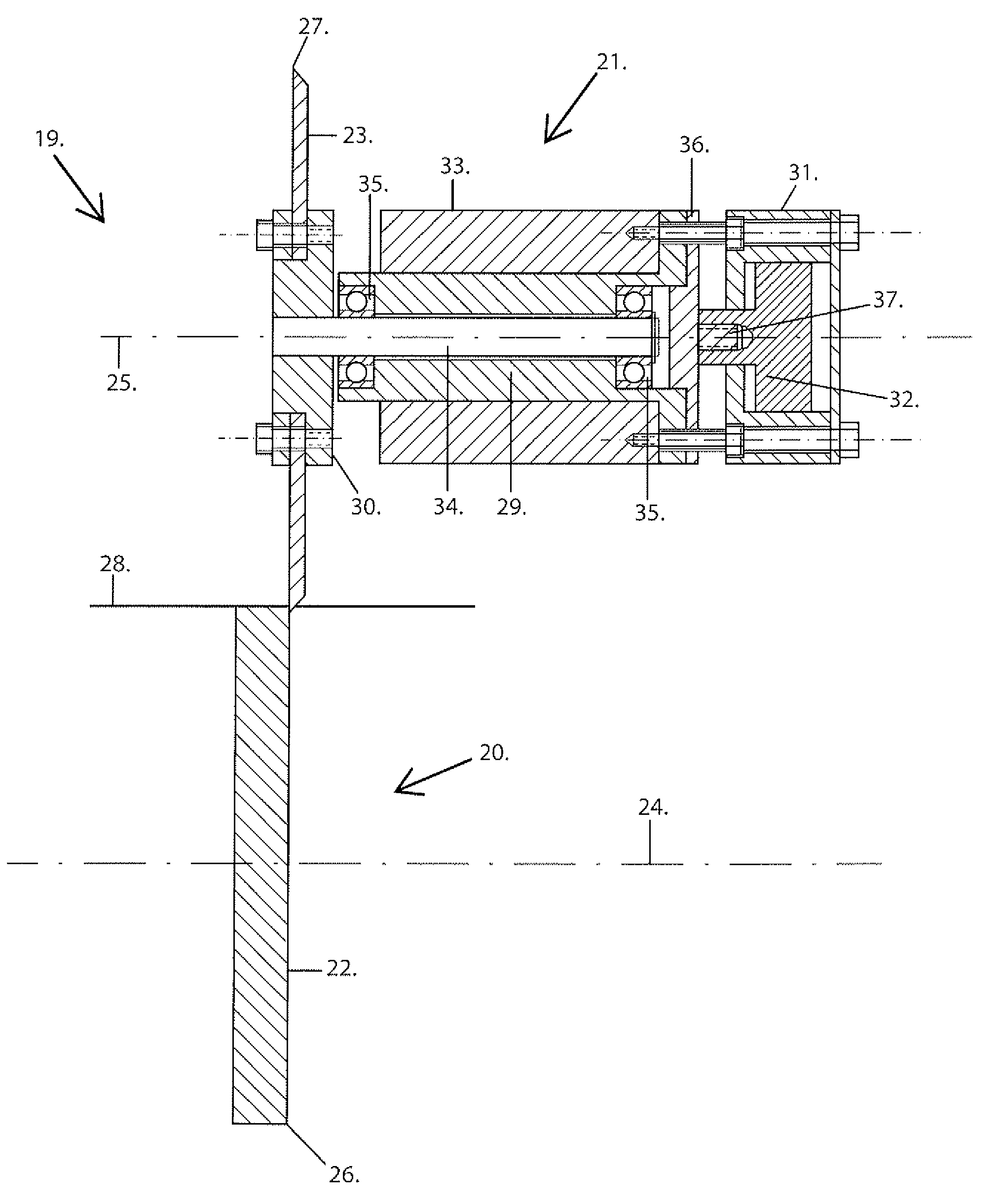
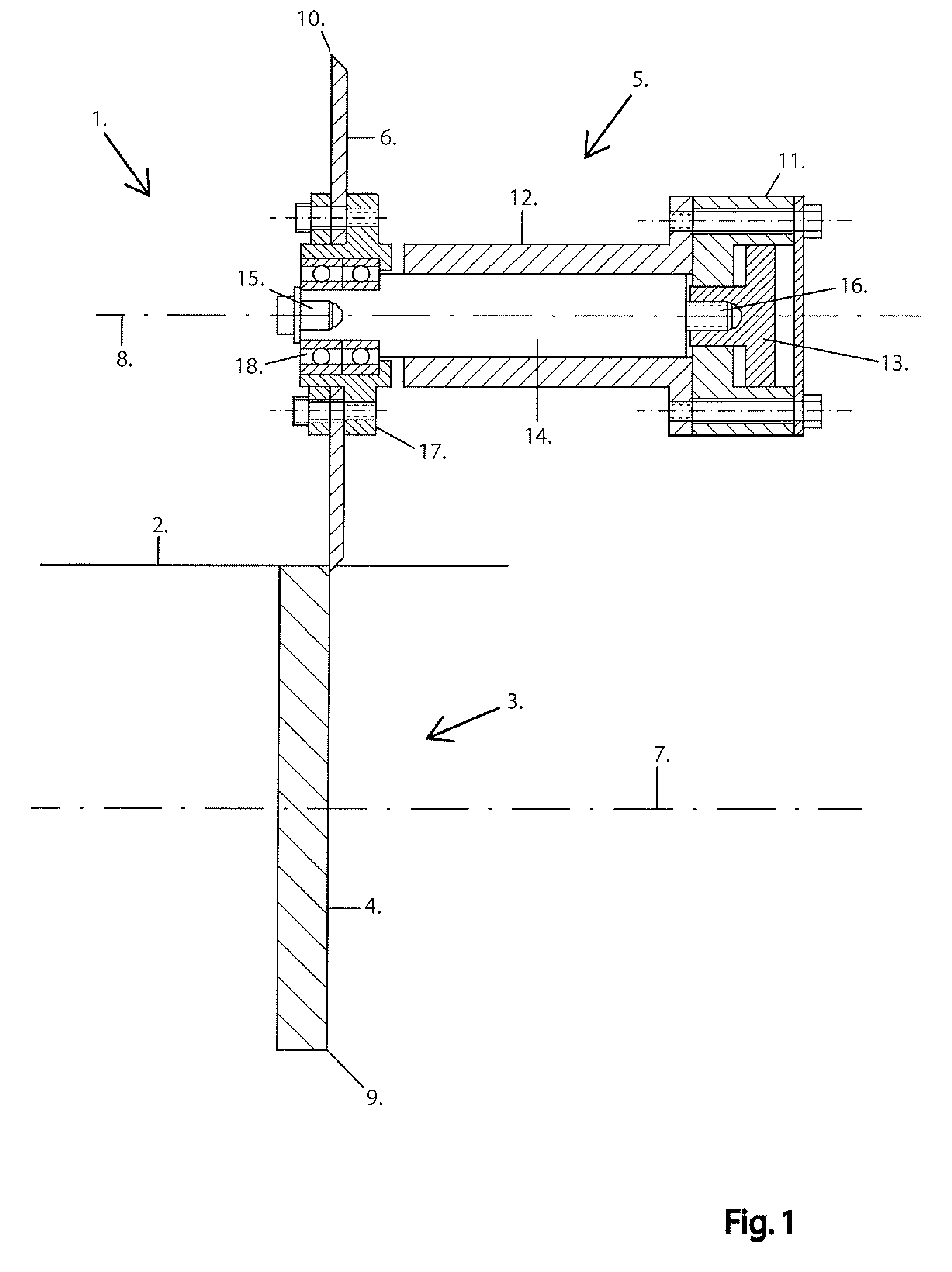
[0012]FIG. 1 shows a cutting device (1) for lengthwise cutting of a moving paper web (2) in a machine to manufacture or process paper. Such a machine can, for example, be a paper machine, coiling machine or a converting machine. The cutting device (1) in part includes a bottom knife (3), which includes an initial, lower circular knife pulley (4), in part an upper knife (5) which includes a second, lower circular knife pulley (6). The lower knife (3) is situated beneath the paper web (2) and the upper knife (5) above the same, and the paper web (2) thus runs between the knives (3), (5). The knife pulleys (4), (6) are rotatable on their own rotation axes (7), (8), said rotation axes (7), (8) are parallel and extend in the paper web's (2) crosswise direction. Each knife pulley (4), (6) has an edge in its periphery (9), (10), which goes around the knife pulleys (4), (6) in a circular direction. In the cutting device's (1) cutting position, shown in FIG. 1, the knife pulley (4), (6) edge...


PUM

PropertyMeasurementUnit
Flexibilityaaaaaaaaaa

Abstract

Cutting device (1) for lengthwise cutting of a moving, flexible web (2) containing an initial knife pulley (4), a second knife pulley (6) and a cylinder (11) with a moving piston (13), said second knife pulley being adjustable relative to the first knife pulley subject to the compressive force from the piston to bring the edge of the second knife pulley (10) to work with the edge of the first knife pulley (9). According to the invention, the cutting device has a slide (14) that is situated between the second knife pulley and the cylinder, said slide being adjustable in the axial direction of the second knife pulley and connected to the piston to follow its movement, and in which slide the second knife pulley has been rotatively stored.

Description

[0001]This invention relates to a cutting device for lengthwise cutting of a moving web of a flexible material, said cutting device including an initial knife pulley, a second knife pulley and a cylinder which includes a moving piston, said second knife pulley, subject to a compressive force from the piston, is adjustable in an axial direction relative to the first knife pulley to bring the second knife pulley edge to work with the first knife pulley edge.[0002]The invention also relates to a machine for manufacturing or processing a paper web, said machine including a cutting device of the type mentioned above for lengthwise cutting of the paper web.[0003]The invention also relates to a method for using a cutting device to cut a moving web of a flexible material, said cutting device including an initial knife pulley, a second knife pulley which is coordinated with the first knife pulley, and a cylinder containing a moving piston, said method including the stage that a compressive f...

Claims


Application Information

Patent Timeline
IPC IPC(8): B26D1/00B26D5/12
CPCB26D1/245B26D5/04B26D7/2635B65H35/02Y10T83/8858Y10T83/04Y10T83/8835B65H35/00
Inventor GREEN, BERT-INGE
Owner STORA ENSO AB
Why Eureka
Try Eureka