Driving Assistance System And Connected Vehicles

a technology of assistance system and connected vehicle, which is applied in the direction of trailer steering, instruments, image enhancement, etc., can solve the problems of comparatively difficult to drive, expensive system as a whole, and the driver is difficult to recognize the rear end of the trailer as the tractor moves, so as to facilitate the driving of a vehicle inexpensively and satisfactorily, the significance and benefits of the invention will be clear

Inactive Publication Date: 2010-07-08
SANYO ELECTRIC CO LTD
View PDF7 Cites 137 Cited by
  • Summary
  • Abstract
  • Description
  • Claims
  • Application Information

AI Technical Summary

Benefits of technology

[0018]According to the present invention, it is possible to assist the driving of a vehicle inexpensively and satisfactorily.
[0019]The significance and benefits of the invention will be clearer from the following description of its embodiments. It should however be understood that these embodiments are merely examples of how the invention is implemented, and that the meanings of the terms used to describe the invention and its features are not limited to the specific ones in which they are used in the description of the embodiments.

Problems solved by technology

In particular, articulated vehicles, composed of a tractor and a trailer towed by the tractor, are comparatively difficult to drive, and thus they benefit well from driving assistance using a camera.
In this type of articulated vehicle, the trailer can swivel about a coupling as a pivot, and this makes it difficult for the driver to recognize how the rear end of the trailer moves as the tractor moves.
Disadvantageously, however, this technology absolutely requires two cameras, leading to an expensive system as a whole.

Method used


Image

  • Driving Assistance System And Connected Vehicles
  • Driving Assistance System And Connected Vehicles
  • Driving Assistance System And Connected Vehicles

Examples


example 1

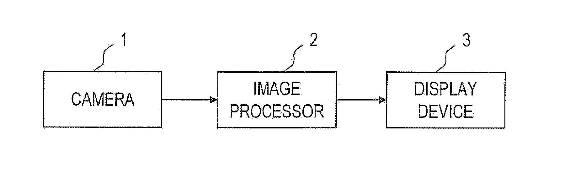
[0081]First, Example 1 will be described. The image processor 2 in FIG. 1 acquires shot images from the camera 1 at predetermined periods, and generates, from the shot images thus sequentially acquired, one display image after another to output the most recent display image to the display device 3. Thus, the display device 3 displays the most recent display image in a constantly updated fashion.

[0082]Now, with reference to FIG. 7, a flow of operation for generating one display image will be described.FIG. 7 is a flow chart showing a flow of such operation. The processing at steps S11 through S17 shown in FIG. 7 is executed by image processor 2 in FIG. 1.

[0083]To generate a display image according to, and characteristic of, the present invention, it is necessary to have a plurality of shot images shot at different time points. Accordingly, the image processor 2 acquires a plurality of shot images shot at different time points, and refers to those shot images in later processing (step...

example 2

[0116]The movement information of the trailer 12 to be determined at step S13 in FIG. 7 is represented by the vector VB in FIG. 11, and determining the movement vector V31 and / or V32 makes it possible to derive the vector VB. Accordingly, at steps S12 and S13 in FIG. 7, the following processing may instead be executed. This modified example of the processing at steps S12 and S13 will now be described as Example 2. In Example 2, the vector VB is derived through the processing for extracting and tracking characteristic points. This derivation method may be considered to be included in the method for deriving the vector VB described with regard to Example 1. Example 2 is implemented in combination with Example 1, and unless inconsistent, any feature described with regard to Example 1 applies to this practical example.

[0117]In Example 2, after the shot images at time points t1 and t2 are acquired at step S11, at step S12, characteristic points are extracted from the shot image at time p...

example 3

[0123]In Example 1, the display image is generated by superimposing vehicle guide lines on the bird's-eye view image. Since the bird's-eye view image is an image as seen when looking down to the ground surface from right above, it has the disadvantage of a narrow field of view. As an alternative, therefore, the display image may be generated by superimposing vehicle guide lines on an image other than the bird's-eye view image. This will now be described as Example 3. Specifically, for example, vehicle guide lines may be superimposed on the shot image as a source image, thereby to generate the display image. This makes it possible to offer an image with a wide field of view. Example 3 is implemented in combination with Example 1 or 2, and unless inconsistent, any feature described with regard to Example 1 or 2 applies to this practical example.

[0124]In Example 3, the vehicle guide lines determined through steps S11 through S16 in FIG. 7 are mapped onto the coordinate system of the sh...


PUM


Abstract

A tractor and a trailer are connected together and a camera is installed on the trailer side of the connected vehicles. The camera captures images behind the trailer. A driving assistance system projects the captured images on bird's-eye view coordinates parallel with a road surface to convert the images into bird's-eye view images and obtains on the bird's-eye view coordinates an optical flow of a moving image composed of the captured images. The connection angle between the tractor and the trailer is estimated based on the optical flow and on movement information on the tractor, and further, a predicted movement trajectory of the trailer is obtained from both the connection angle and the movement information on the tractor. The predicted movement trajectory is overlaid on the bird's-eye view images and the resulting image is outputted to a display device.

Description

TECHNICAL FIELD[0001]The present invention relates to a driving assistance system for assisting the driving of an articulated vehicle (coupled, or connected vehicles), and also relates to an articulated vehicle employing such a driving assistance system.BACKGROUND ART[0002]In recent years, with increasing awareness for safety, more and more vehicles have come to be equipped with a camera. This tendency applies not only to ordinary passenger vehicles but also to industrial vehicles. In particular, articulated vehicles, composed of a tractor and a trailer towed by the tractor, are comparatively difficult to drive, and thus they benefit well from driving assistance using a camera. In this type of articulated vehicle, the trailer can swivel about a coupling as a pivot, and this makes it difficult for the driver to recognize how the rear end of the trailer moves as the tractor moves.[0003]Under this background, there have been proposed several technologies for assisting the driving of ar...

Claims


Application Information

Patent Timeline
Patent Type & Authority Applications(United States)
IPC IPC(8): H04N7/18
CPCB60R1/00B60R2300/607B60R2300/806B60R2300/8086G06T2207/10016G06T2207/30241G06T2207/30264H04N7/183B62D13/06B62D15/0275G06T7/246
Inventor ISHII, YOHEII
Owner SANYO ELECTRIC CO LTD
Why Eureka
Try Eureka