Structure and method of assembly thereof

a technology of structure and assembly method, applied in the direction of wood veneer joining, dismountable cabinets, manufacturing tools, etc., can solve the problems of reduced productivity, difficult and confusing process, and substantial time and mental effor

Active Publication Date: 2010-07-08
THERMWOOD CORPORATION
View PDF2 Cites 137 Cited by
  • Summary
  • Abstract
  • Description
  • Claims
  • Application Information

AI Technical Summary

Problems solved by technology

In this positioning effort, the software generally only considers the size and shape of each part, and does not consider the cabinets in the job for which the part is used.
This can be a difficult and confusing process, especially when assembling more complex cases with internal shelves and partitions.
This requires substantial time and mental effort, and materially reduced productivity.
This often results in cabinets being assembled incorrectly.

Method used


Image

  • Structure and method of assembly thereof
  • Structure and method of assembly thereof
  • Structure and method of assembly thereof

Examples


Embodiment Construction

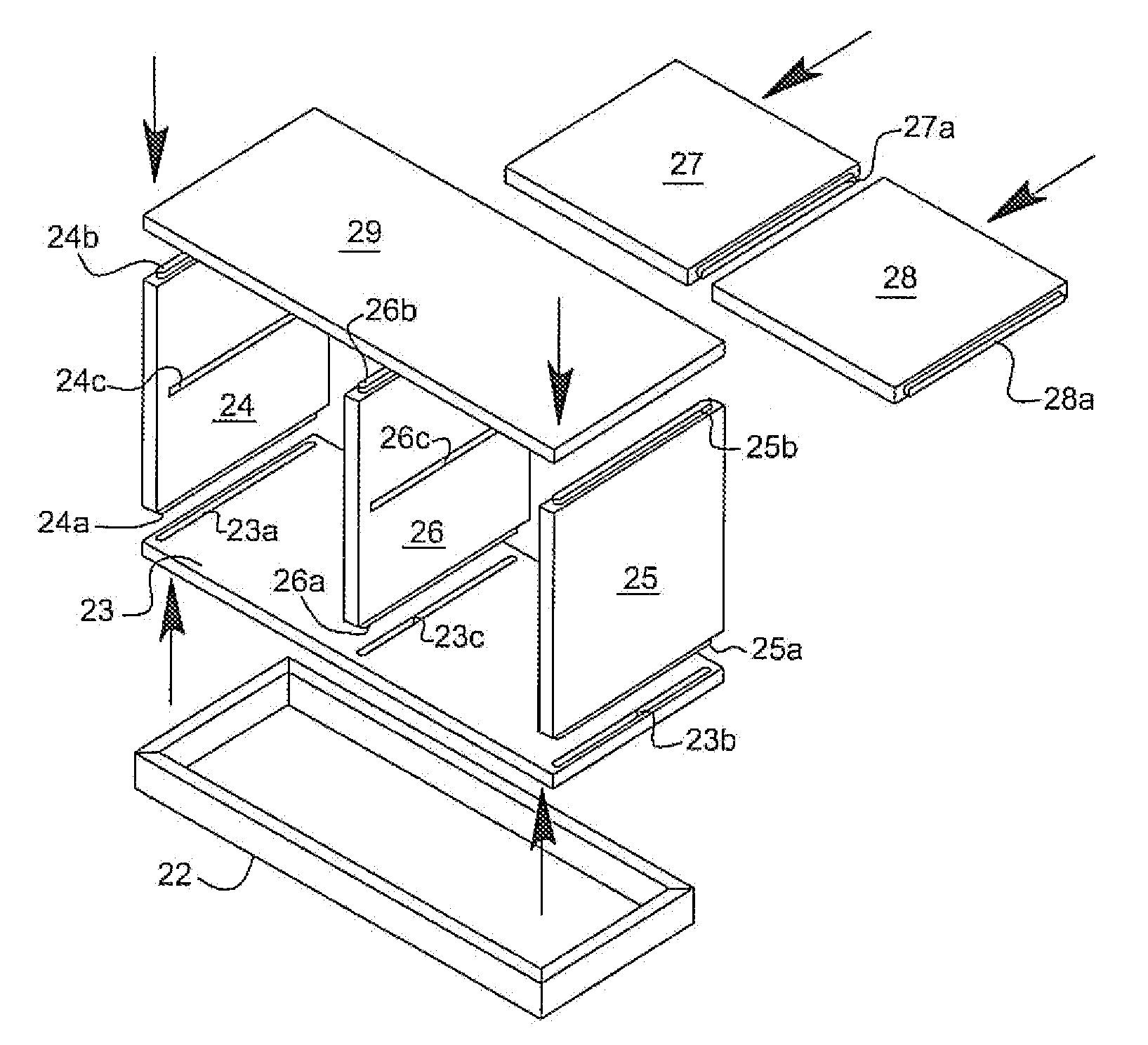
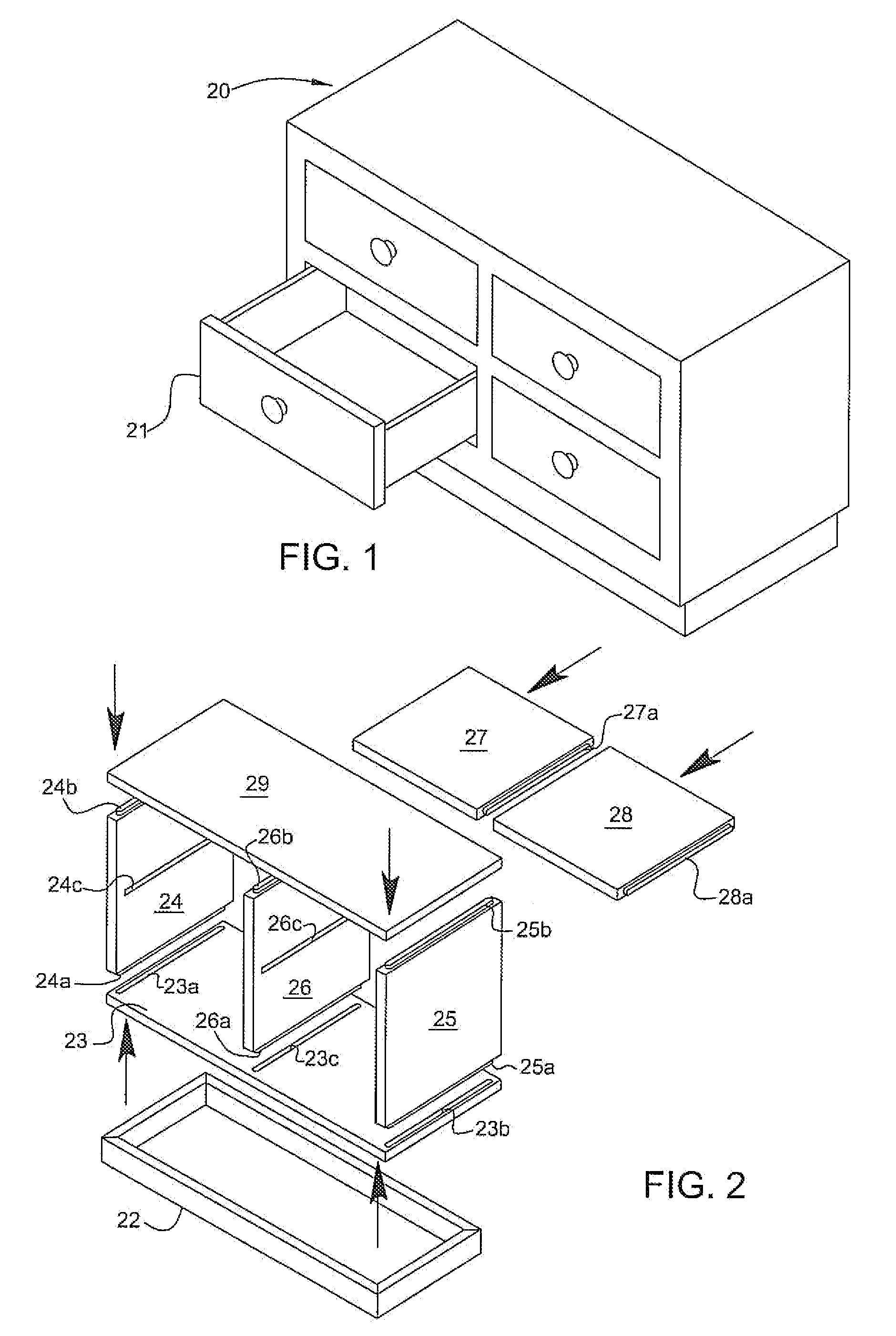
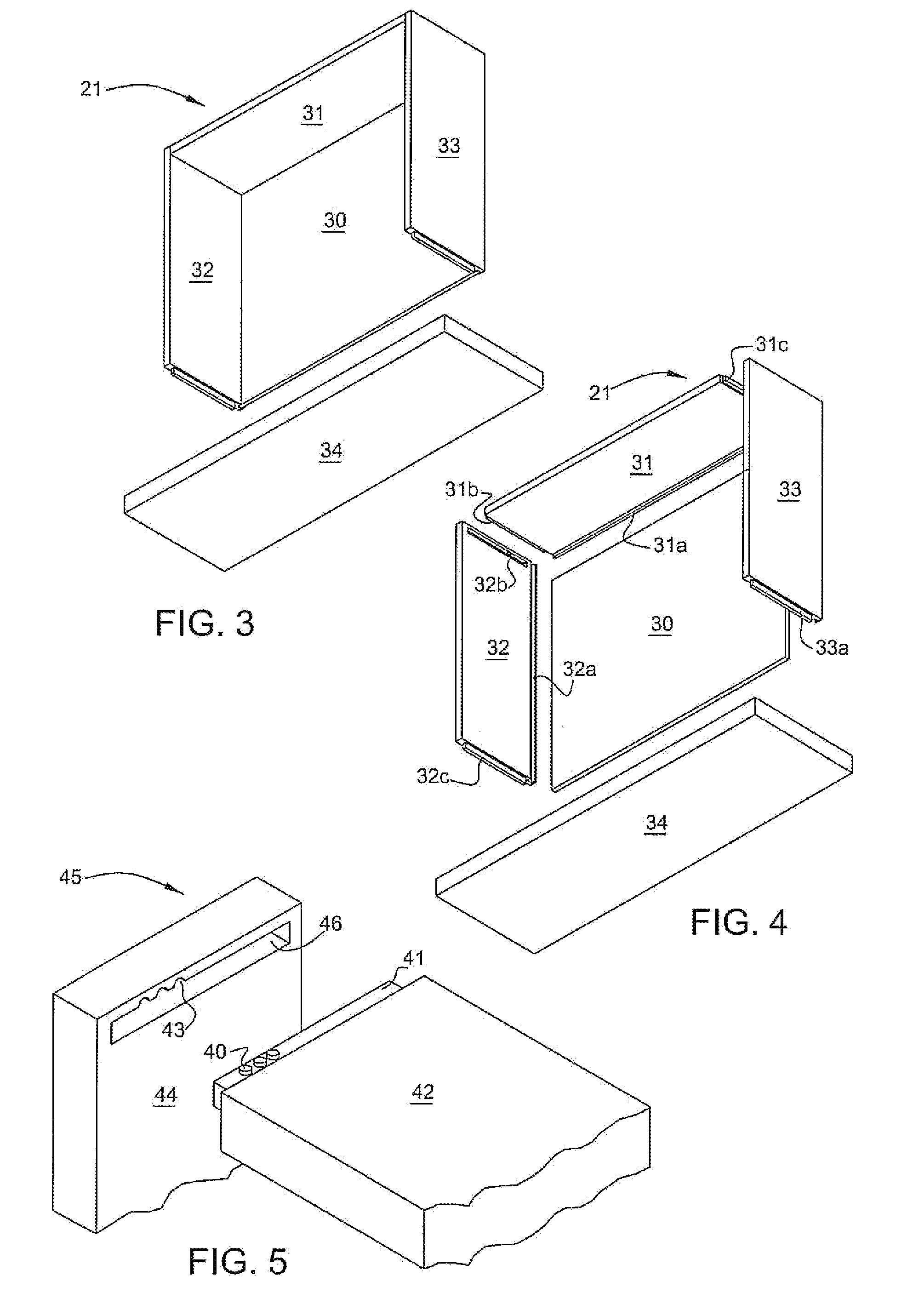
[0018]Referring to FIG. 1 of the drawings, there is illustrated a cabinet 20 provided with a set of drawers 21, assembled with the component workpieces shown in FIGS. 2 through 4, in accordance with the present invention. As shown in FIG. 2, the component pieces of the cabinet include a rectangular base 22, a bottom panel 23, a pair of side panels 24 and 25, a partition panel 26, a pair of shelf panels 27 and 28 and a top panel 29. As shown in FIGS. 3 and 4, each drawer 21 is comprised of a bottom panel 30, a rear panel 31, a pair of side panels 32 and 33 and a front panel 34.

[0019]The component panels as described are secured together by means of a mortise formed in one piece and either a side edge or tenon of an adjoining piece being received in such mortise and secured by gluing. With respect to the cabinet, bottom panel 23 is provided mortises 23a and 23b adjacent the side edges thereof, and a center mortise 23c. Side panel 24 is provided with a lower edge tenon 24a insertable i...


PUM

PropertyMeasurementUnit
lengthsaaaaaaaaaa
lengthsaaaaaaaaaa
lengthsaaaaaaaaaa

Abstract

A method of forming an assembly including a first workpiece having a surface provided with a mortise and a second workpiece provided with a tenon inserted into the mortise joining the workpieces together in which the second workpiece is disposed in a certain orientation relative to the first workpiece to provide a certain disposition of the workpieces when joined together, generally consisting of providing identifying marks on the surface of the first workpiece and the tenon of the second workpiece at locations assuming a certain disposition when the second workpiece is disposed in a certain orientation and the tenon is registered with the mortise; positioning the second workpiece relative to the first workpiece wherein the second workpiece is disposed in the certain orientation relative to the first workpiece, the tenon is registered with the mortise and the marks are disposed in the certain mark disposition; and displacing the second workpiece toward the first workpiece and inserting the tenon into the mortise.

Description

[0001]This invention relates to a method of assembling a number of workpieces in forming a structure such as a cabinet, and a structure formed by such method.BACKGROUND OF THE INVENTION[0002]Kitchen cabinets are constructed primarily from wood-based sheet material such as plywood, medium density fiberboard, commonly referred to as MDF, particleboard or chip core. These sheet materials are generally comprised of sheets of sliced wood veneer laminated together or wood materials ground and then pressed into sheets of a consistent thickness. They are available in various widths and lengths with four foot by eight foot, four foot by ten foot, five foot by eight foot and five foot by ten foot being common standard sizes available in the United States from a variety of sources.[0003]A common method of processing these sheets into cabinet components is to place the entire sheet of material on the worktable of a computer controlled machine called a CNC router, and then cut out the various pa...

Claims


Application Information

Patent Timeline
Patent Type & Authority Applications(United States)
IPC IPC(8): B32B7/00B27F1/00B27F5/00A47B47/00
CPCA47B47/042A47B67/04F16B12/125Y10T428/24174Y10T29/49899Y10T29/49833Y10T29/49901Y10T29/49826Y10T29/49895Y10T29/49995
Inventor SUSNJARA, KENNETH J.
Owner THERMWOOD CORPORATION
Why Eureka
Try Eureka