Downhole Separator

a separator and downhole technology, applied in the field of downhole tools, can solve the problems of pump efficiency and pump damage, and achieve the effect of reducing the cross-sectional flow area

Active Publication Date: 2010-07-15
COBB DELWIN E
View PDF17 Cites 33 Cited by
  • Summary
  • Abstract
  • Description
  • Claims
  • Application Information

AI Technical Summary

Problems solved by technology

Solid particles, such as sand, and / or gas bubbles may significantly detract from the efficiency of the pump, and may lead to pump damage.

Method used


Image

  • Downhole Separator
  • Downhole Separator
  • Downhole Separator

Examples


Embodiment Construction

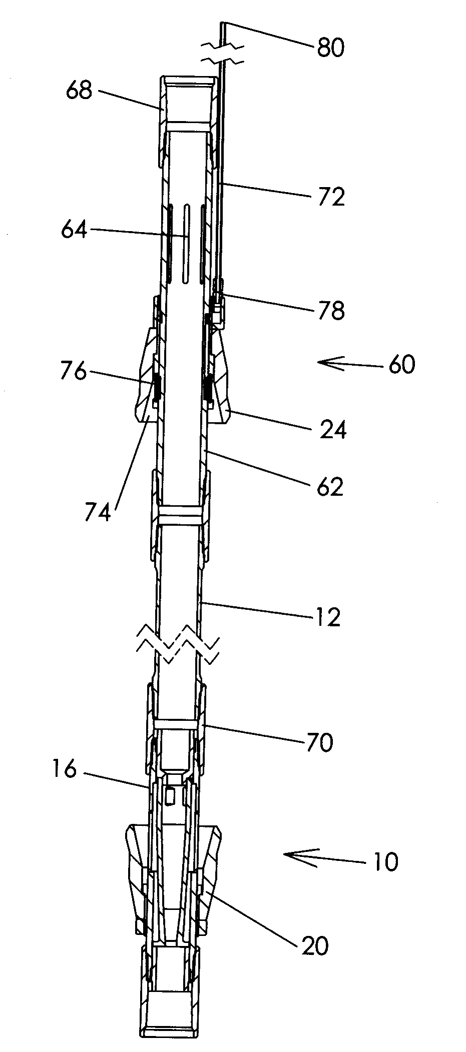
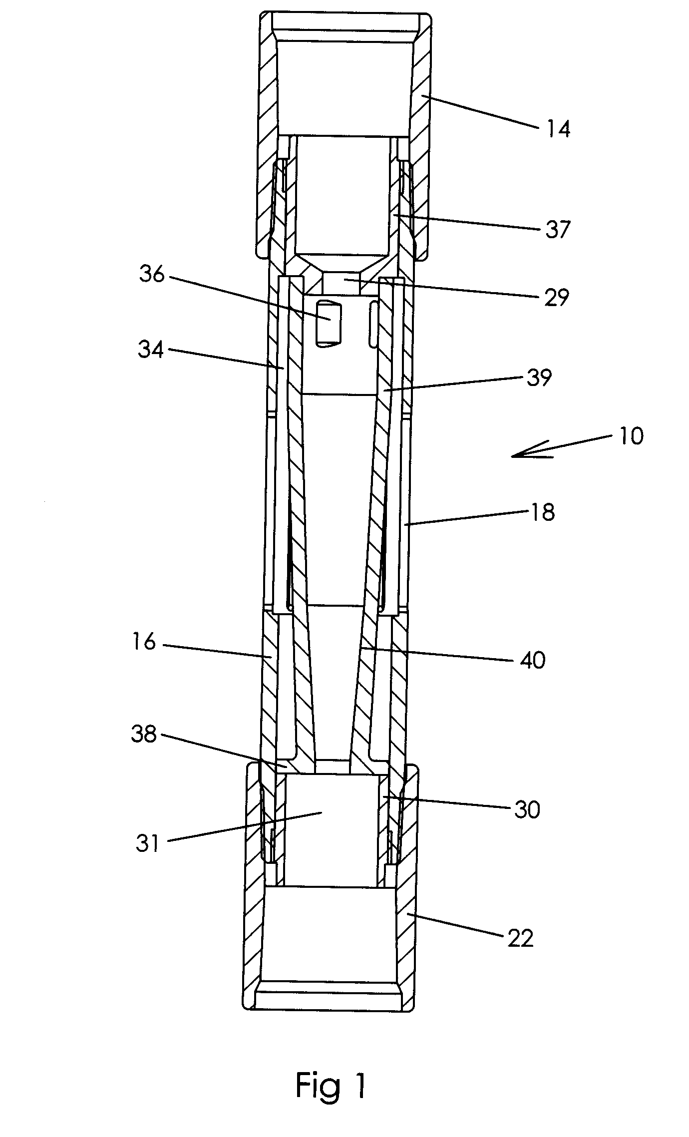
[0020]FIG. 1 illustrates a desander 10 which comprises outer desander body 16 and coupling 14 for interconnecting a pup joint with the desander body 16 and an inner vortex body 39. The desander body 16 includes the plurality of circumferentially spaced fluid inlets 18. The upper end of the desander body is adapted for connection to the pup joint, or may be directly connected to a production tubing string.

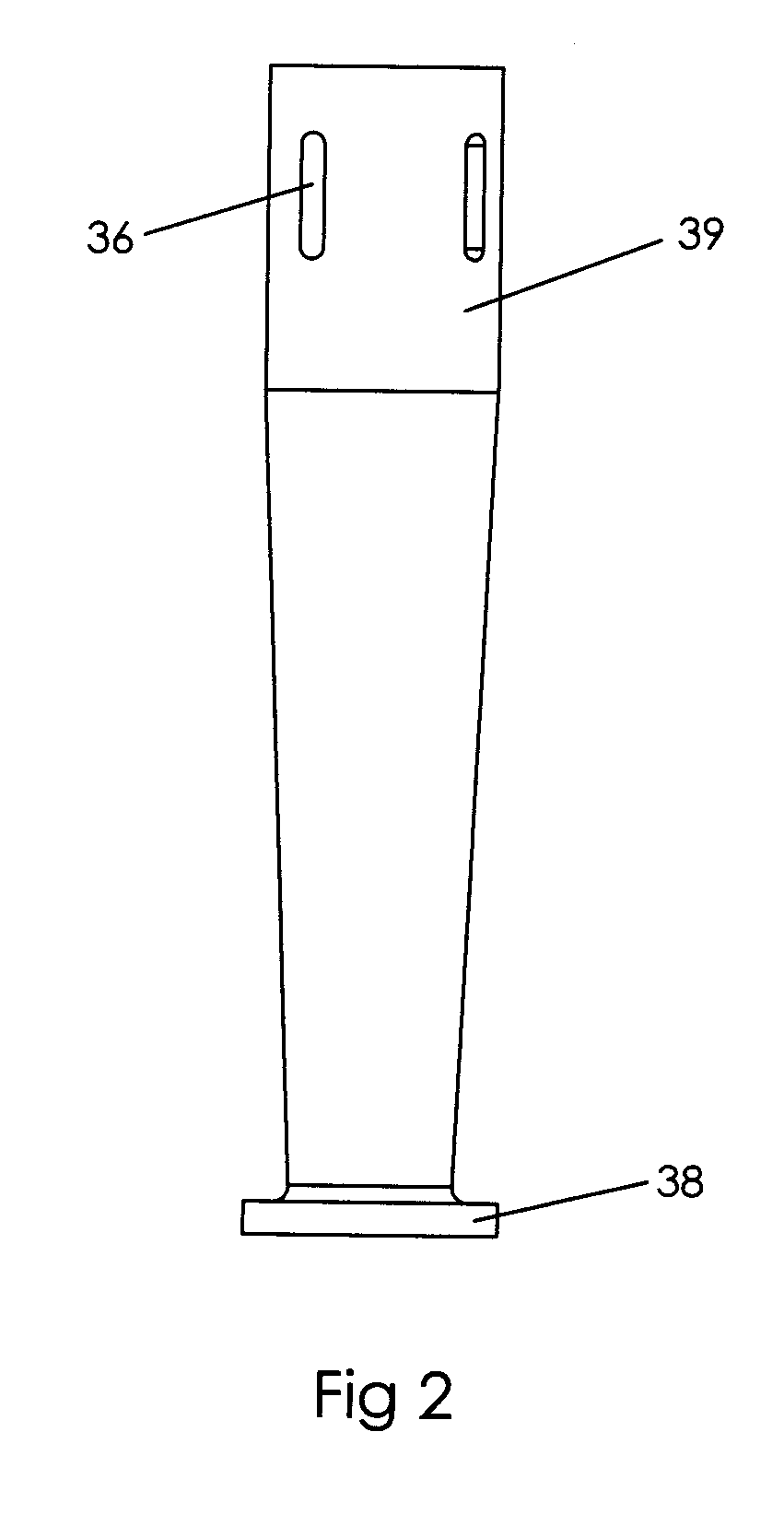
[0021]Body 16 is threaded at its upper end for interconnection with the coupling 14, and is threaded at its lower end for interconnection with coupling 22. An annular gap 34 exists between an interior of the body 16 and exterior of the vortex body 39. Flow enters through fluid inlets 18 and flows upward through the one or more ports 36 in the vortex body 39. End port 36 may have a generally rectilinear configuration for high flow rates and sound structural integrity for the vortex body. Solids are forced radially outward within the vortex body and fall into the mud anchor, while liq...


PUM

PropertyMeasurementUnit
diameteraaaaaaaaaa
areaaaaaaaaaaa
pressureaaaaaaaaaa

Abstract

The desander (10) for positioning downhole includes a generally tubular desander body (16) and a generally sleeve-shaped vortex body (39, 94). The desander with a seal or packer may be positioned in a well below the casing perforations. The desander with an ESP may be used with gas separator (60), which may include a seal (24) for positioning above the producing formation. The separator (60) may be used independent of the desander for some applications.

Description

FIELD OF THE INVENTION[0001]The present invention relates to a downhole tool used to separate sand and similar solid particles from a fluid stream before the fluid is pumped to the surface. This invention may also involve a gas separator to separate gas from liquids.BACKGROUND OF THE INVENTION[0002]Various types of pumping systems have been devised to pump fluid from a downhole formation to the surface. Solid particles, such as sand, and / or gas bubbles may significantly detract from the efficiency of the pump, and may lead to pump damage. Various types of desanders and gas separators have been devised for removing sand or gas from downhole fluids before entering the pump.[0003]U.S. Pat. No. 6,234,248 discloses well production apparatus which includes a gas fluid separator in the casing of the well. A fluids composition sensor and transmitter are also provided. U.S. Pat. No. 6,723,158 discloses another type of gas separator with a single large gas exit port and a single large fluid i...

Claims


Application Information

Patent Timeline
Patent Type & Authority Applications(United States)
IPC IPC(8): E21B43/38E21B43/34B01D19/00B01D21/26
CPCB04C5/081B04C5/28B01D21/267B01D45/12E21B43/38E21B43/35
Inventor COBB, DELWIN E.
Owner COBB DELWIN E
Why Eureka
Try Eureka