Method and devices for stabilizing electric grid power

a technology for stabilizing electric grid power and power supply, applied in emergency protective circuit arrangements, electric devices, etc., can solve problems such as affecting the overall stability of an aging north american electrical grid, increasing the number of uncontrolled high current surges, and disrupting the power flow to end users

Inactive Publication Date: 2010-07-15
GRID LOGIC
View PDF7 Cites 49 Cited by
  • Summary
  • Abstract
  • Description
  • Claims
  • Application Information

AI Technical Summary

Benefits of technology

[0023]The invention also provides a method of stabilizing electric power, including detecting a fault in a grid using a first variable impedance device, inserting a current limiting impedance in a first path of the grid using the first variable impedance device near the fault, transmitting a signal from the first variable impedance device to a second variable impedance device following detection of the fault, receiving the signal at the second variable impedance device and inserting a current limiting impedance in a second path of the grid using the second variable impedance device in response to receiving the signal.

Problems solved by technology

Increasing electrical demand, grid interconnections and a growing number of independent power generation facilities have decreased the overall stability of an aging North American electrical grid.
This instability frequently manifests itself as an increase in the number of uncontrolled high current surges (i.e. fault currents), which result from flooding, high winds, downed tree limbs, lightning strikes, crossed transmission lines, etc.
Left unchecked, fault currents may permanently damage transmission and distribution equipment, trip high-power circuit breakers, and disrupt power flow to end users, causing considerable social and economic impact in the afflicted regions.
Reliable, albeit inefficient and bulky, alternative fault control methods (e.g. fast circuit breakers, air core reactors, high impedance transformers, etc.) are typically used in the electrical transmission and distribution grid since high-efficiency, economical fault current limiting devices have yet to be developed.
Unfortunately, prototype HTS-based superconducting FCLs have had limited success because of the poor HTS materials properties, the low critical currents of HTS wire and bulk components, and the inherent high cost of the HTS components.
Similar to HTS materials, however, MgB2 is a hard, brittle ceramic material, and suffers many of the same mechanical shortcomings as the HTS ceramics.
To date, HTS and MgB2 superconducting materials do not yet possess the physical and economic characteristics necessary to develop cost-effective, reliable superconducting FCL systems.

Method used


Image

  • Method and devices for stabilizing electric grid power
  • Method and devices for stabilizing electric grid power
  • Method and devices for stabilizing electric grid power

Examples


Embodiment Construction

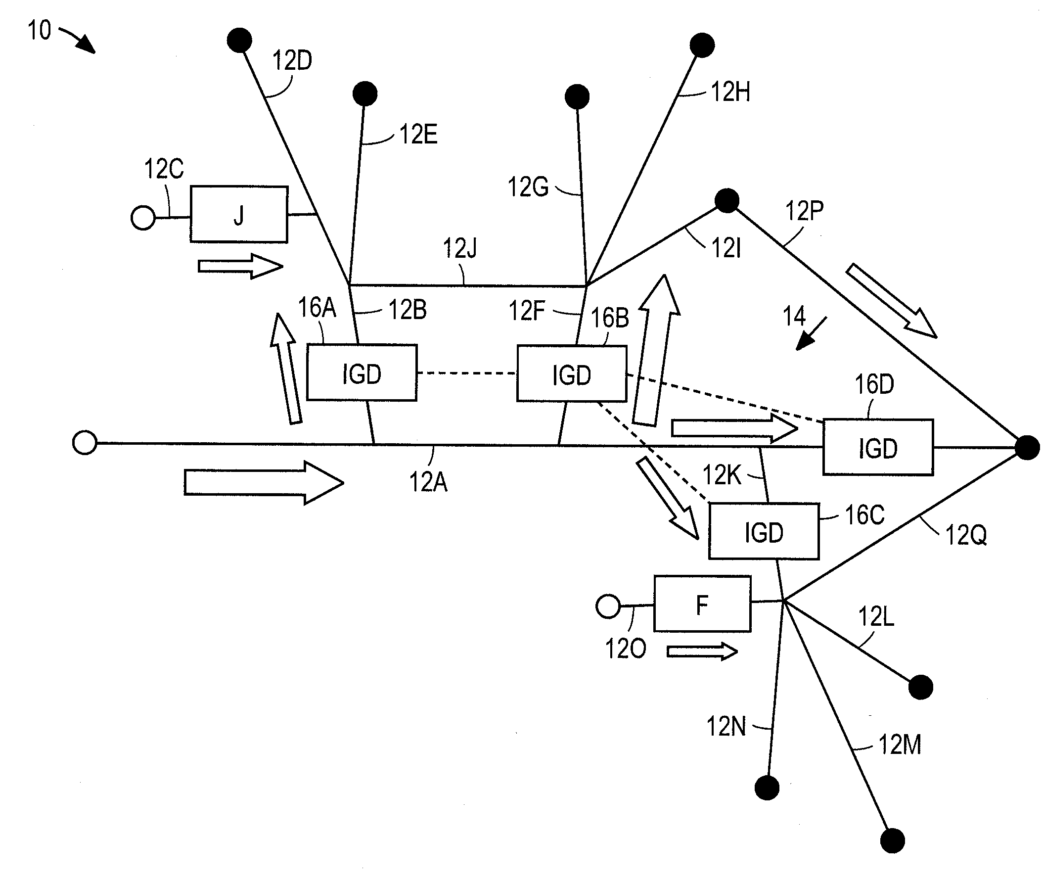
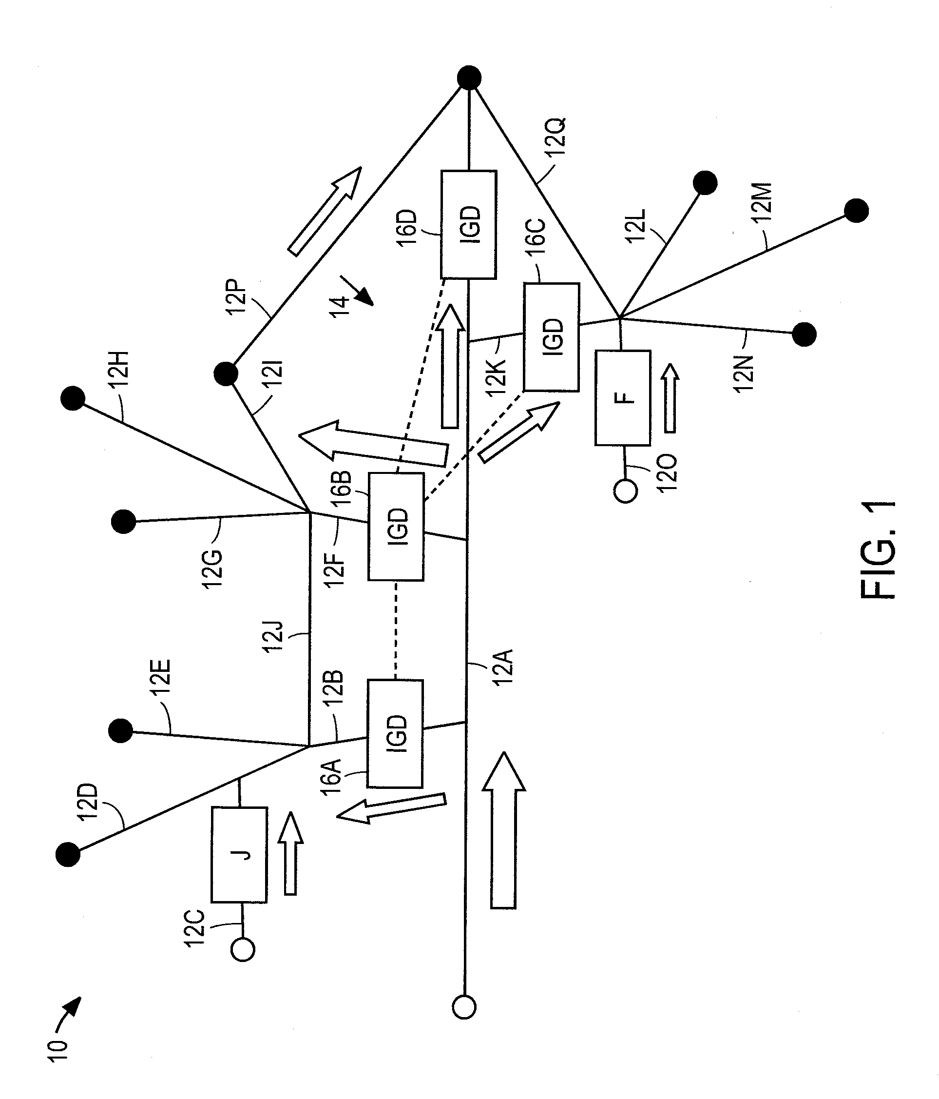
[0051]FIG. 1 of the accompanying drawings illustrates an electric grid 10 including a plurality of connected electric paths 12A-G and an electric grid stabilization metadevice 14.

[0052]The electric grid stabilization metadevice 14 includes a plurality of IGDs 16A-16D. The IGDs 16A-16D are located within the electric paths 12B, 12F, 12K and 12A, respectively. The IGD 16A has the ability to switch between a mode wherein superconductor current passes through the IGD 16A and a mode wherein the IGD 16A inserts a current limiting impedance into the electric path 12B while still allowing current to flow through the electric path 12B. The IGD 16A can passively detect a fault downstream of the electric path 12B, for example in the path 12D and switch from the mode wherein superconductor current is carried through the IGD 16A and the mode wherein the IGD 16A inserts a current limiting impedance in the electric path 12B.

[0053]The IGD 16A also has transmission and reception capabilities. When a...


PUM


Abstract

The invention provides an electric grid stabilization metadevice including a plurality of interactive grid devices each forming part of a respective electrical path of an electric grid and each including, a variable impedance device that inserts a current limiting impedance in the respective path when a fault occurs, a state detection transducer connected to the variable impedance device to change a detection state when the fault occurs and an integral communications system having transmission and reception capabilities and being connected to the state detection transducer and variable impedance device, wherein a fault detected by each of the interactive grid devices automatically causes transmission of a signal to another integrated grid device, reception of the signal by the other integrated grid device and an insertion of a current limiting impedance by the other integrated grid device.

Description

CROSS-REFERENCE TO RELATED APPLICATIONS[0001]This application claims priority from U.S. Provisional Patent Application No. 61 / 204,898, filed on Jan. 12, 2009, which is incorporated herein by reference in its entirety.BACKGROUND OF THE INVENTION[0002]The present invention relates to the control of the electric utility grid through the use of variable impedance devices that respond automatically to destabilizing transients in the electric grid, or respond under active control to improve grid stabilization and power quality.[0003]The efficient and reliable generation, transmission and distribution of electrical power is essential to the security and economy of the United States. Increasing electrical demand, grid interconnections and a growing number of independent power generation facilities have decreased the overall stability of an aging North American electrical grid. This instability frequently manifests itself as an increase in the number of uncontrolled high current surges (i.e....

Claims


Application Information

Patent Timeline
Patent Type & Authority Applications(United States)
IPC IPC(8): H02H7/00H02H9/00
CPCY02E40/69H02H9/023Y02E40/60
Inventor HOLCOMB, MATTHEW J.CARAVIAS, GEORGE
Owner GRID LOGIC
Why Eureka
Try Eureka