Generating an erosion image utilizing parallel pixel processing

a technology of image processing and pixel processing, applied in image analysis, image enhancement, instruments, etc., can solve the problems of adding additional processing time, and time-consuming conventional erosion process, etc., and achieve the effect of generating an erosion imag

Inactive Publication Date: 2010-07-15
CANON KK
View PDF11 Cites 6 Cited by
  • Summary
  • Abstract
  • Description
  • Claims
  • Application Information

AI Technical Summary

Benefits of technology

[0012]By virtue of the foregoing arrangement, it is possible to generate an erosion image from a corresponding input digital image faster than with a traditional sequential approach, enabling real-time, fast fps, hi-resolution image processing and analysis, while producing an erosion image substantially similar to an erosion image produced using a traditional sequential approach. For example, by utilizing parallel processing to generate an erosion image according to the foregoing arrangement, a 2K×2K digital image can be processed at speeds of 250 fps, which is much faster than the 0.20 fps obtained by the traditional sequential approach.

Problems solved by technology

Thus, the conventional erosion process can be time consuming depending on the size of the image.
In this regard, the additional extended pixels are required to be processed in the sequential processing, thereby adding additional processing time.
One problem with the foregoing conventional erosion image process is that each pixel of the image is processed sequentially during both the binarization process and during the erosion processes.
Another problem is that the binarization, extension, erosion and clipping process are each performed in sequence.
As a result, the time needed to generate the erosion image increases with the size of the digital image.
Thus, very high resolution images (e.g., a 2048×2048, or 2K×2K, pixel digital image) require a greater amount of time to process.

Method used


Image

  • Generating an erosion image utilizing parallel pixel processing
  • Generating an erosion image utilizing parallel pixel processing
  • Generating an erosion image utilizing parallel pixel processing

Examples


Embodiment Construction

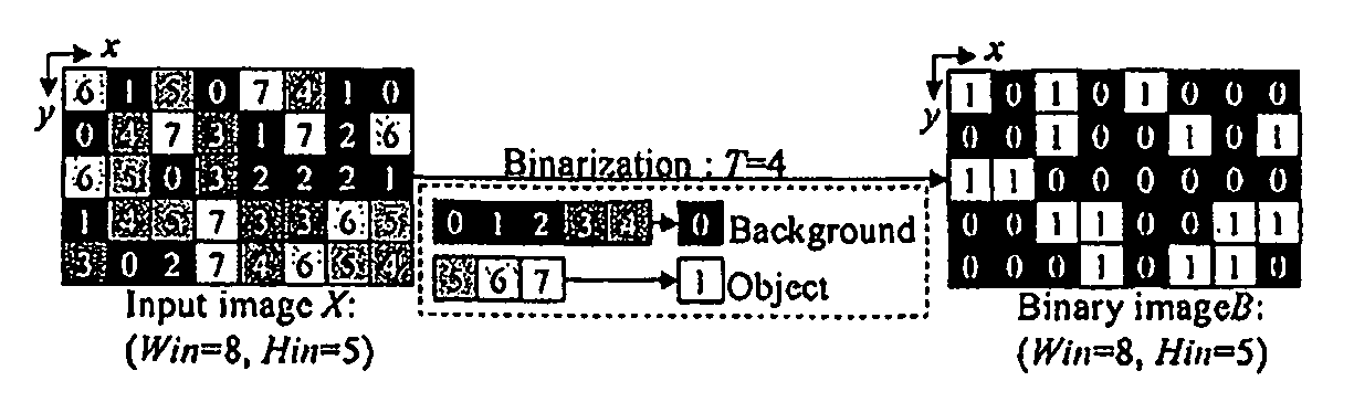
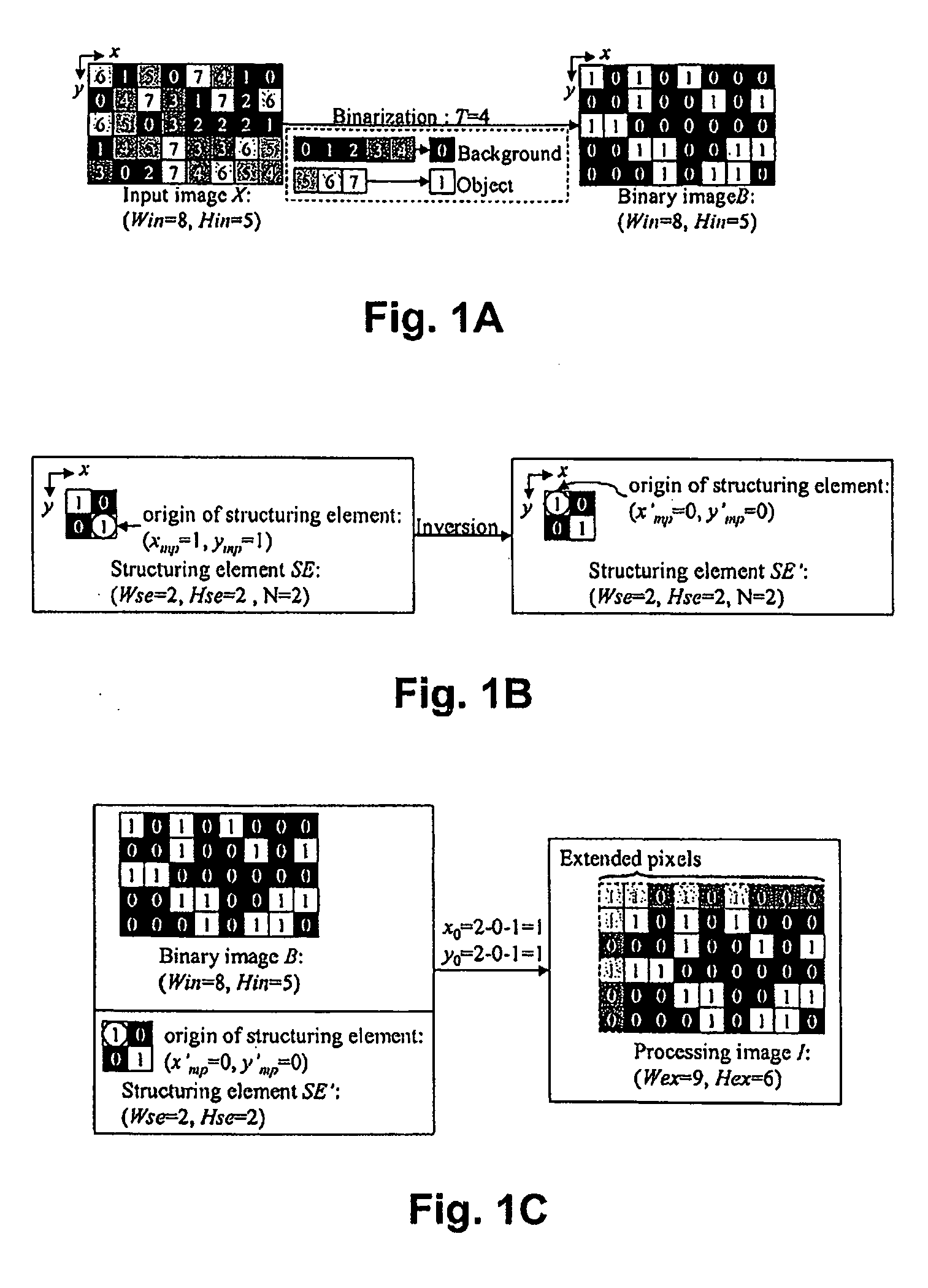
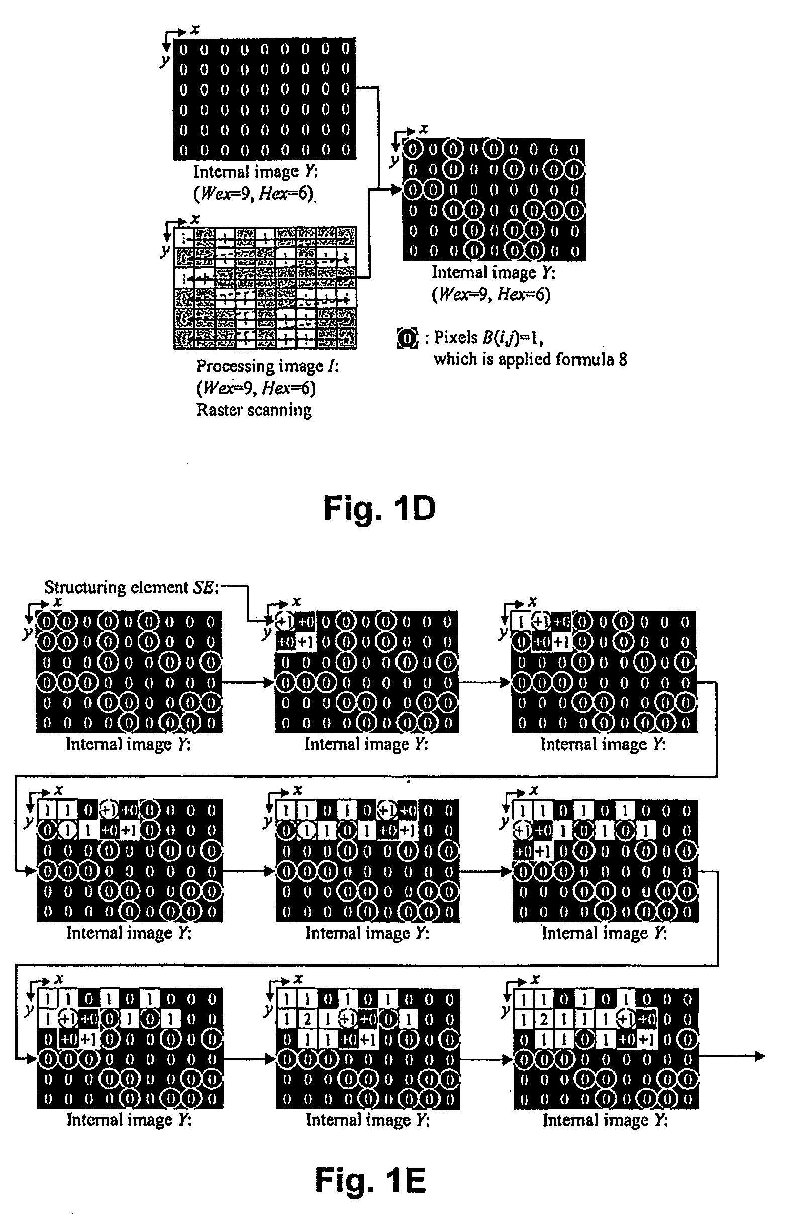
[0040]FIG. 2 depicts an example of a computing environment in which the invention may be employed. Briefly, the invention is directed to performing image processing to generate and output an erosion image from an original input image. By way of example, various implementations of the invention may be inputting an original image from any one of a number of devices, such as a digital image generated by an x-ray machine, a tomogram, satellite image, digital photograph, or virtually any digital image source, and then applying the process of the invention to the input original image to obtain an erosion (thinned-out) image that is then output to a display device, a printer, etc. Thus, as seen in FIG. 2, the invention may be employed in an environment that includes personal computer workstation 10 or laptop computer 20 that may be connected to a network 11 which is preferably a world wide network such as the Internet, but may also be local area network (LAN). In this manner, computer work...


PUM


Abstract

An erosion image is generated from an original digital image utilizing a processing image (b) and a target image (T), where each pixel in the target image is processed in parallel. The process entails, for each target pixel, i) determining coordinate values for the target pixel, ii) determining a surrounding pixel area for the target pixel, iii) and processing each pixel in the surrounding pixel area to determine whether or not to updated the value of the target pixel. In processing each surrounding pixel, a determination is made whether the pixel has a value of 1. If not, then the next surrounding pixel is processed. If so, then a determination is made which pixel element of a structuring element overlays the target pixel, and whether that SE pixel has a value of 1. If so, then the value of the target pixel is updated. If not, then the next pixel in the surrounding pixel area is processed. Once the target pixel has been updated a set number of times to a predetermined value (e.g., 2), the processing of the remaining surrounding pixels is terminated. After all target pixels have been processed, an output image is obtained by setting target pixels having a value of 2 to a binary value of 1, and setting the other pixels to a binary value of 0. The resultant output image is an erosion image that is then output.

Description

BACKGROUND OF THE INVENTION[0001]1. Field of the Invention[0002]The invention generally relates to image processing techniques for generating an erosion image, and more specifically relates to performing morphology of a digital image utilizing parallel binarization processing of each pixel of an image, and performing parallel processing of each pixel in a target image to obtain an erosion image.[0003]2. Description of the Related Art[0004]Conventionally, an erosion image is generated from an input image in four steps: binarization, extension, erosion, and clipping, where each step is performed sequentially and the binarization and erosion processes are performed on each pixel of the input image in sequence. For example, in the binarization step, each pixel of the input image is binarized in sequence utilizing a threshold value for each pixel. The result is a binarized image in which each pixel is represented by either a 0 or a 1. The binarization process typically is performed by sc...

Claims


Application Information

Patent Timeline
Patent Type & Authority Applications(United States)
IPC IPC(8): G06K9/42
CPCG06K9/00986G06K9/342G06T2207/20148G06T7/0091G06T2207/20036G06T7/0081G06T7/11G06T7/155G06T7/136G06V10/955G06V10/267
Inventor BAJO, ALLISONMATHEW, MANOJ
Owner CANON KK
Why Eureka
Try Eureka