External fixator assembly

Inactive Publication Date: 2010-07-15
MDPO LLC
View PDF31 Cites 43 Cited by
  • Summary
  • Abstract
  • Description
  • Claims
  • Application Information

AI Technical Summary

Benefits of technology

[0016]As represented hereinafter in greater detail, the external fixator assembly, including the support structure of the present invention, is structured to connect one or more transfixion pins or like transfixion members so as to extend transversely inward and into stabilizing engagement with the leg bone(s) or other tissue associated with the ankle area at various points along the height or length of the leg and/or ankle area. Further, each of the one or more transfixion pins can be connected to a plurality of different locations along the length thereof. Therefore the disposition of the base and extension assembly of the support structure as well as the structure of at least some of the remainder of the external fixation assembly provides significant versatility in positioning each of the one or more transfixion p

Problems solved by technology

In utilizing these support blocks, transfixion clamps, etc., one commonly recognized problem or disadvantage associated therewith is the possibility these devices obscuring important or necessary portions of the ankle joint when X-rayed.
In addition, the proper placement of one or more of such

Method used


Image

  • External fixator assembly
  • External fixator assembly
  • External fixator assembly

Examples


Embodiment Construction

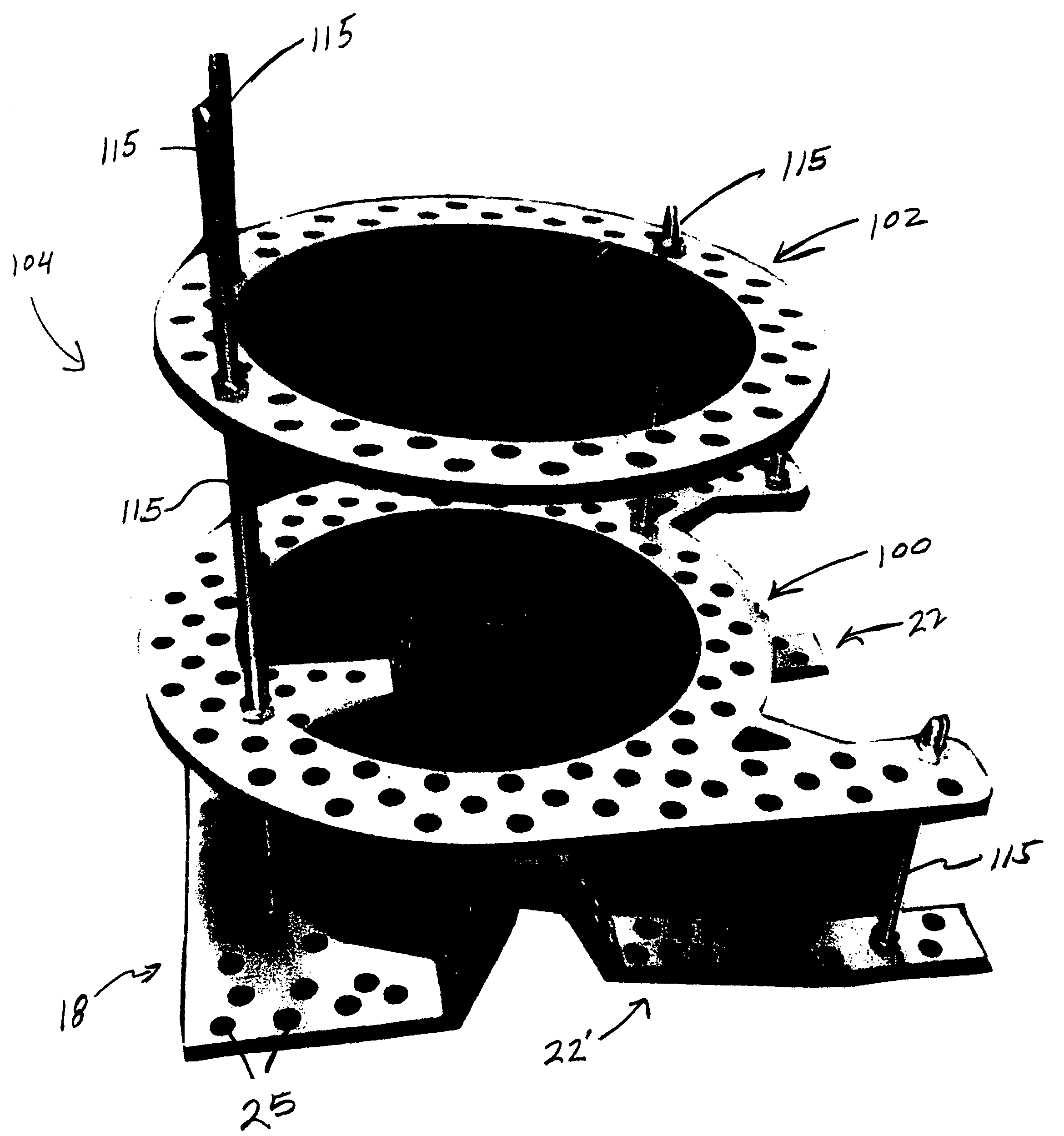
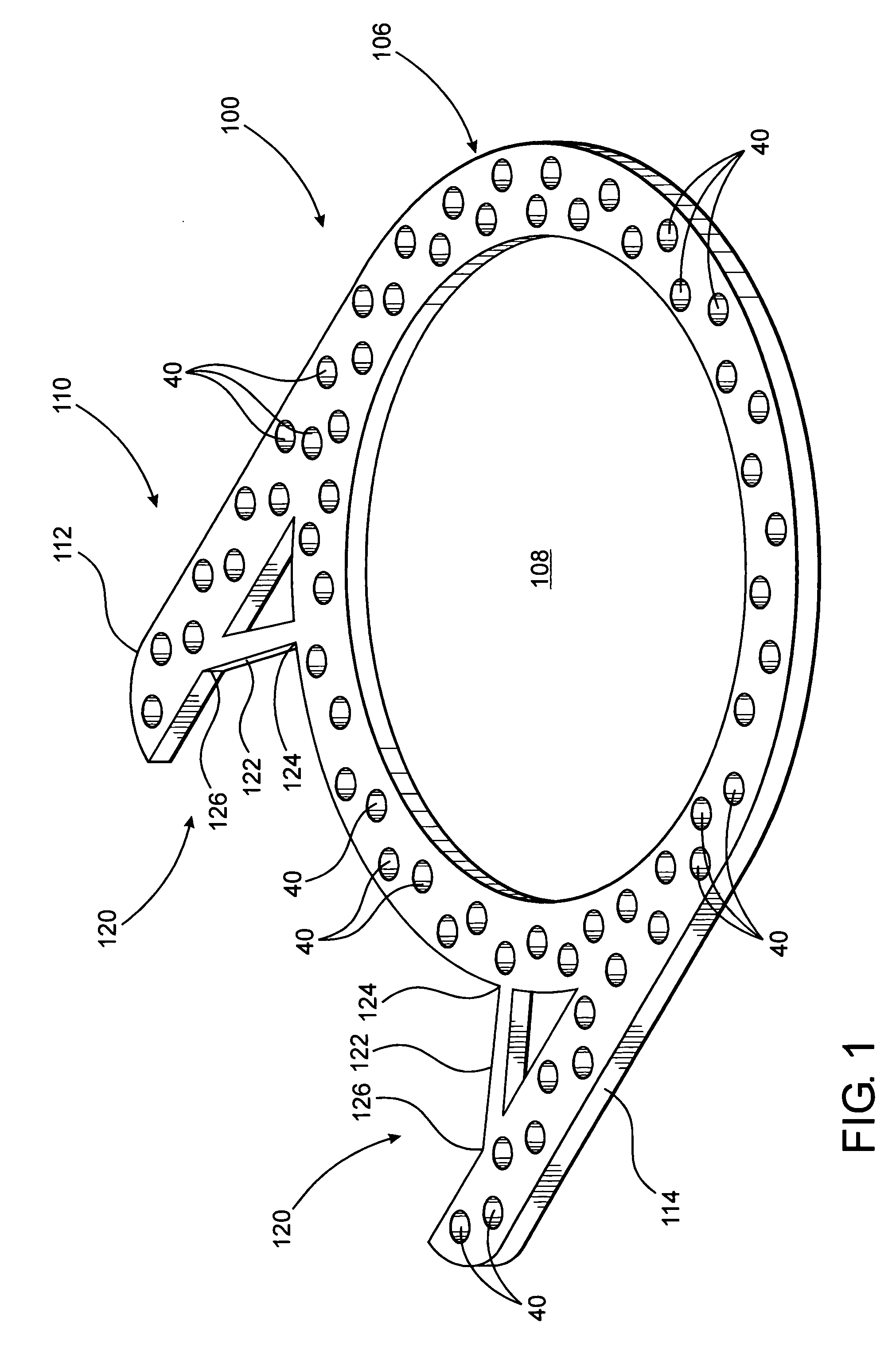
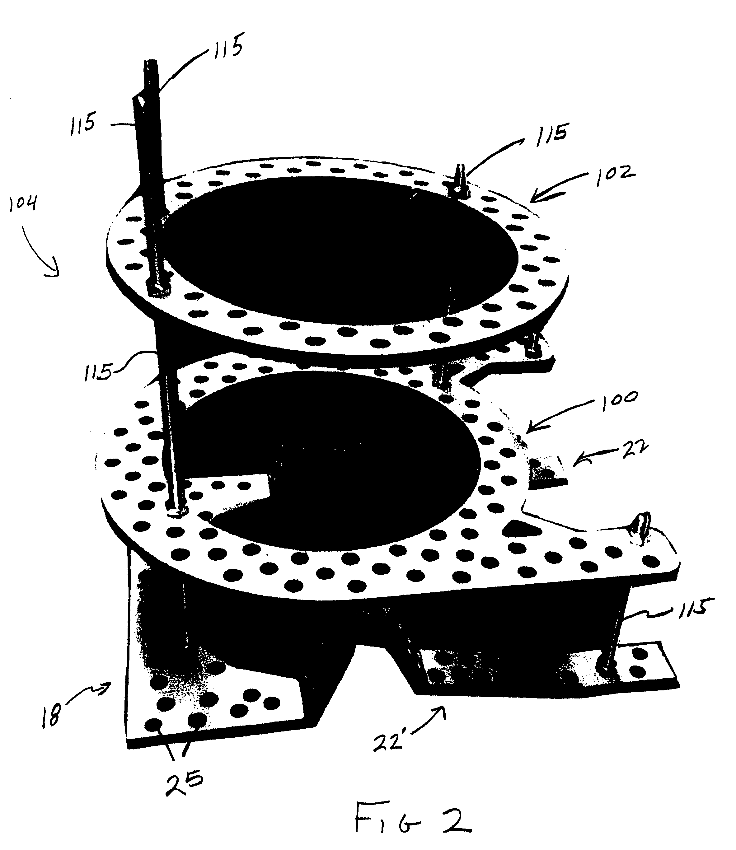
[0027]As represented in the accompanying Figures, the support assembly of the present invention is generally indicated as 100 and is structurally distinguishable from the conventional halo support ring generally indicated as 102 in the embodiments of FIGS. 2-4. Moreover, each of a plurality of preferred embodiments of the support structure ring 100 of the present invention is adaptable for use in combination with an external fixation assembly generally indicated as 104 in the embodiments of FIGS. 2-4. Further, as will also be discussed in greater detail hereinafter, the external fixator assembly 104 is structured to be operatively positioned and used in a location substantially adjacent to an ankle area generally indicated as 12 in FIG. 5 of a patient. As set forth above, the ankle area 12 is meant to be descriptive of substantially the entire area represented in FIG. 5, which includes the ankle joint, foot, corresponding portions of the leg bones, including the fibula and tibia, as...


PUM


Abstract

A support structure for use with an external fixator assembly including, but not limited to, a fixator assembly for the ankle area of the body which may further include an ankle stabilization portion. The support structure is similar in function but distinguishable in structure from a “halo-ring” and comprises a base having a substantially annular configuration and being operatively disposed in at least partially surrounding relation to a leg area which corresponds to the stabilized ankle area. An extension assembly includes at least one but preferably a plurality of two elongated extension members extending outwardly from the base and in spaced relation to and substantially aligned with the ankle stabilization portion. The base and the two extension members are structured for connection to a plurality of struts which may be variably and selectively disposed in interconnecting relation to the ankle stabilization area and/or other portions of the external fixator assembly.

Description

BACKGROUND OF THE INVENTION[0001]1. Field of the Invention[0002]This invention is directed to a support structure similar in function but distinguishable in structure to a halo-type support ring adapted for use as an operative component of an external fixation assembly for an ankle or other area of the patient's body. The support structure includes an annular base dimensioned and configured for disposition in surrounding relation to a leg area associated with the ankle being stabilized. An extension assembly comprising a plurality of extension members is connected to the base, wherein the base and extension members are structured for connection to one or more strut members disposed in interconnecting relation to and between the support structure and the other components of the external fixator assembly.[0003]2. Description of the Related Art[0004]In the medical treatment of pathologies including, but not limited to, injuries, fractures, etc. to the bone and joints, external fixator ...

Claims


Application Information

Patent Timeline
IPC IPC(8): A61F5/00
CPCA61B17/6425A61B17/62
Inventor MARIN, LUIS E.
Owner MDPO LLC
Why Eureka
Try Eureka