Descent device

a technology of a device and a drop, which is applied in the direction of cleaning equipment, sports equipment, applications, etc., can solve the problems of significant slack generation in the lifeline prior to the centrifugal brake mechanism engaging, and the impact on the lifeline and the associated harness is significant and potentially dangerous

Inactive Publication Date: 2010-07-22
LIFELINE DESCENT SYST
View PDF16 Cites 17 Cited by
  • Summary
  • Abstract
  • Description
  • Claims
  • Application Information

AI Technical Summary

Benefits of technology

[0023]applying a weight to a free end of the lifeline and

Problems solved by technology

A disadvantage of the device of the '395 patent, however, is that substantial slack is generated in the lifeline prior to the centrifugal brake mechanism engagin

Method used


Image

  • Descent device
  • Descent device
  • Descent device

Examples


Embodiment Construction

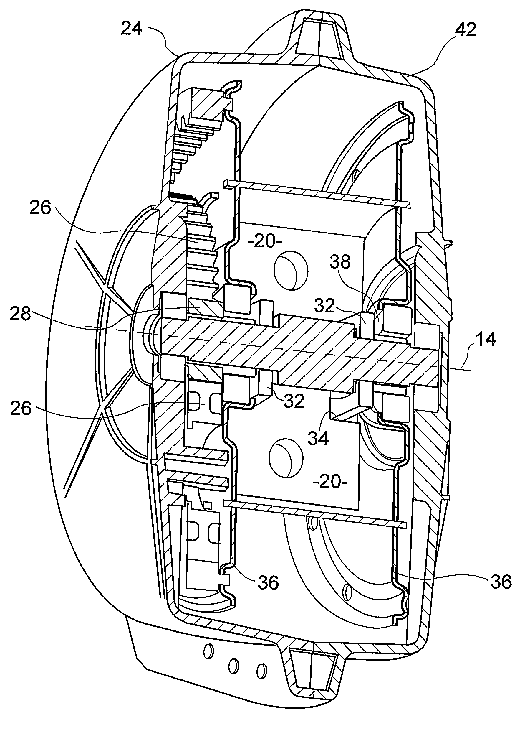
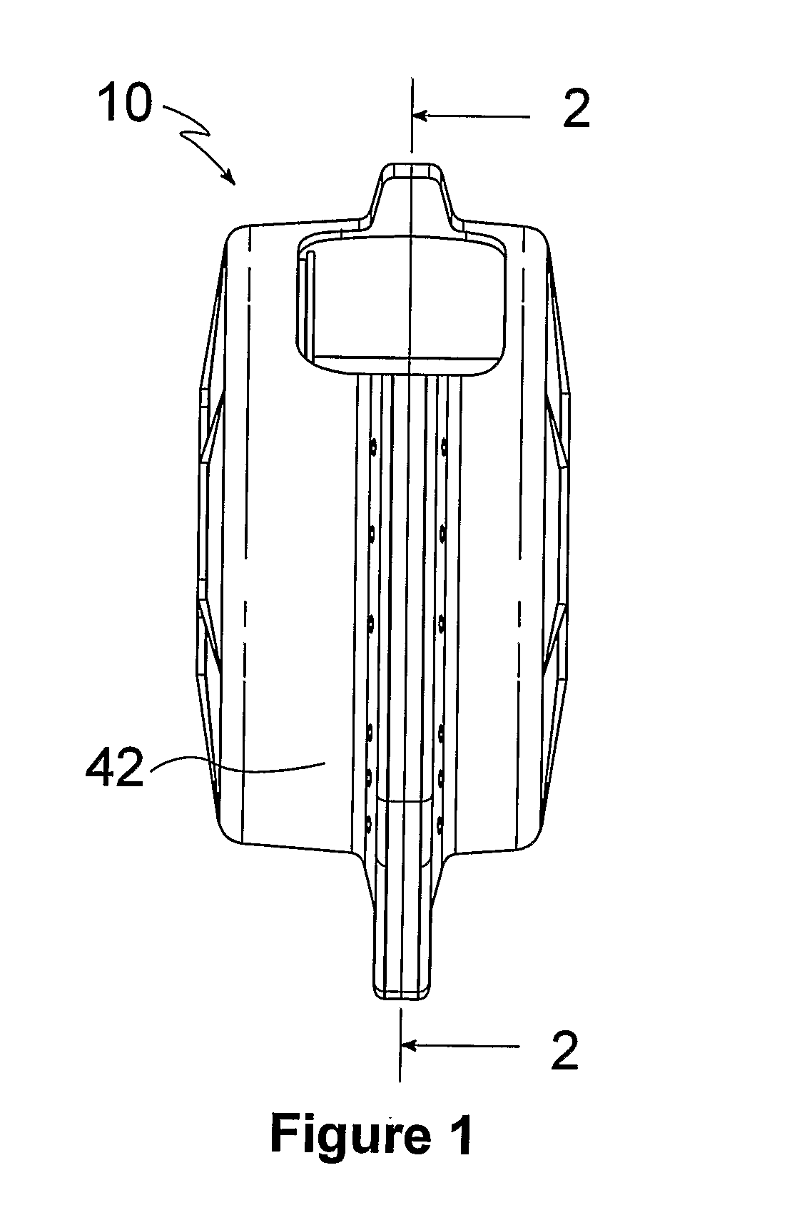
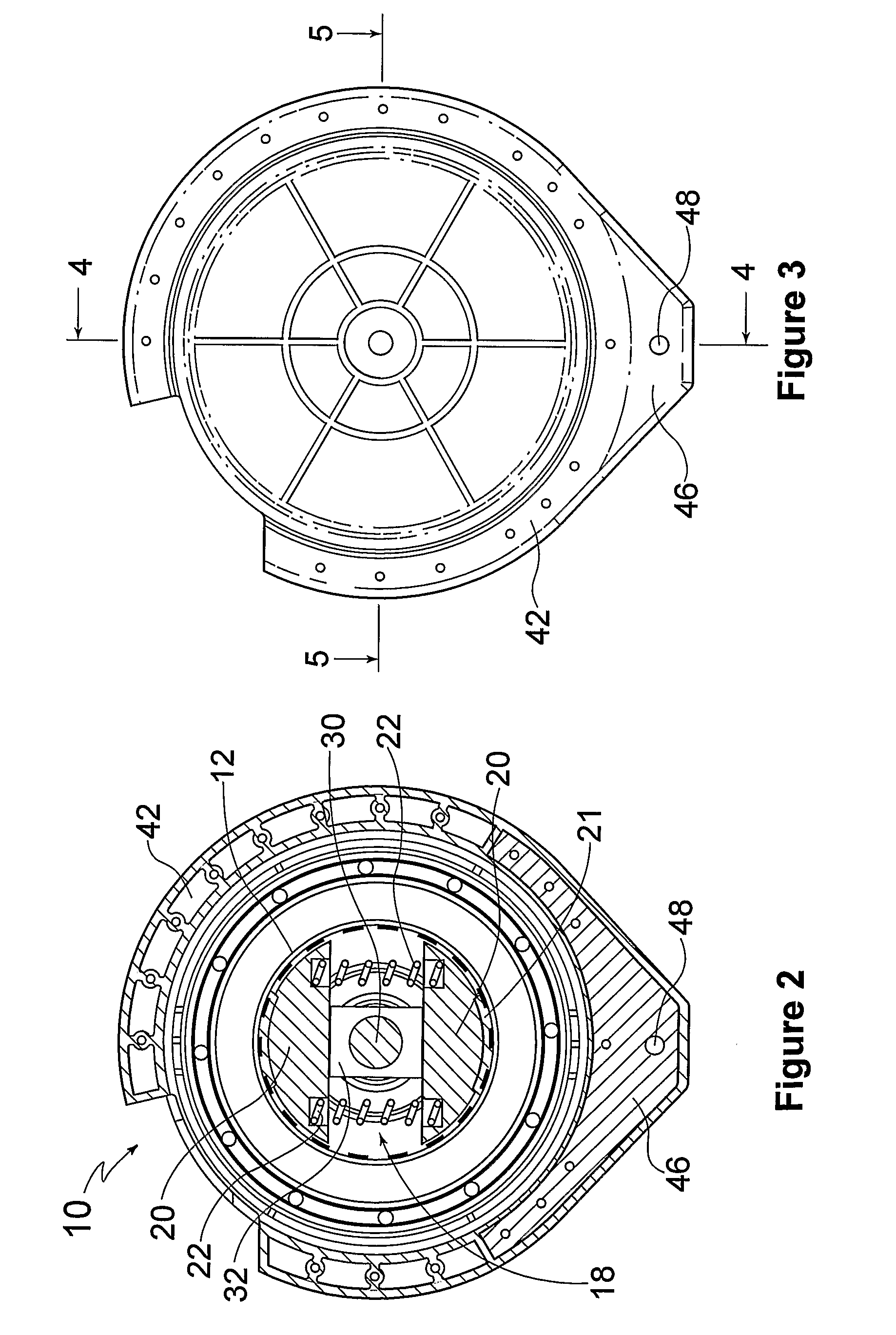
[0033]Referring to the drawings, there is shown a descent device 10 comprising a hollow spool 12 rotatable about a rotational axis 14 and a lifeline, in the form of a braided steel cable (not shown), wound about the spool 12. A centrifugal brake mechanism 18 including a brake assembly, comprising a pair of brake shoes 20 and associated brake pads 21, is engageable with the spool 12 to apply a braking force to the spool 12 as the spool 12 rotates. Biasing members, in the form of a compression springs 22, extend between the brake shoes 20 for biasing the brake shoes 20 and pads 21 into engagement with the spool 12.

[0034]The compression spring 22 is adapted to provide sufficient friction between the spool 12 and the brake pads 21 to prevent rotation of the spool 12 due to the weight of an initially unwound portion of the cable. Accordingly, the spring 22 is adapted to provide a force of between around 10 N and around 100 N between the spool 12 and the brake pads 21.

[0035]The centrifuga...


PUM


Abstract

There is disclosed herein a descent device (10) comprising a hollow spool (12) rotatable about a rotational axis (14) and a lifeline, in the form of a braided steel cable (not shown), wound about the spool (12). A centrifugal brake mechanism (18) including a brake assembly, comprising a pair of brake shoes (20) and associated brake pads (21), is engageable with the spool (12) to apply a braking force to the spool (12) as the spool (12) rotates. Biasing members, in the form of a compression springs (22), extend between the brake shoes (20) for biasing the brake shoes (20) and pads (21) into engagement with the spool (12).

Description

TECHNICAL FIELD[0001]The present invention relates to a device for evacuation of inhabitants from multi-storey buildings and, in particular, to a descent device for allowing inhabitants to lower themselves in a controlled manner from such a building.[0002]The present invention has been developed for use in evacuating inhabitants from multi-storey buildings in emergency situations, such as where lifts and / or stairwells are inoperable, overcrowded or otherwise unusable. However, it will be appreciated that the invention is not limited to this particular field, and may also be used, for example, in construction and maintenance of multi-storey buildings, operation of oil and gas rigs, mountaineering, as well on cranes and operating platforms.BACKGROUND OF THE INVENTION[0003]Known devices for evacuating inhabitants from multi-storey buildings include centrifugal braking devices, such as that disclosed in U.S. Pat. No. 5,076,395. This device includes a lifeline that is selectively dispens...

Claims


Application Information

Patent Timeline
IPC IPC(8): A62B1/10F16H57/08F16D59/00
CPCA62B1/10B66D5/04F16D2127/002F16D51/00B66D5/18
Inventor HOBSON, ERIC
Owner LIFELINE DESCENT SYST
Why Eureka
Try Eureka