Ultrasonic diagnostic apparatus, positional information acquiring method, and computer program product

a positional information and diagnostic apparatus technology, applied in diagnostics, mammography, medical science, etc., can solve the problems of increasing production costs, complex structure of ultrasonic diagnostic apparatus, and inability to easily acquire positional information of ultrasound probes

Inactive Publication Date: 2010-07-22
TOSHIBA MEDICAL SYST CORP
View PDF4 Cites 9 Cited by
  • Summary
  • Abstract
  • Description
  • Claims
  • Application Information

AI Technical Summary

Benefits of technology

[0012]According to an aspect of the present invention, an ultrasonic diagnostic apparatus includes an ultrasound wave control unit that performs control in such a manner that a depth of an ultrasonic wave emitted from an ultrasound probe is set to a value deeper than an observation region of a subject; an image generating unit that generates a plurality of ultrasonic images in chronological order based on a reflection wave of the ultrasonic wave emitted by the ultrasound probe in accordance with the control performed by the ultrasound wave control unit; a positional information acquiring unit that acquires motion information from the ultrasonic images generated by the image generating unit in chronological order, identifies a left organ or a right organ that is being scanned by the ultrasound probe based on an intensity ratio of heartbeat-related motion components and respiration-related motion components in the motion information that is acquired, and acquires an identification result as positional information; and a display control unit that performs control in such a manner than the positional information acquired by the positional information acquiring unit on a predetermined displaying unit.
[0013]According to another aspect of the present invention, an ultrasonic diagnostic apparatus includes an ultrasound wave control unit that performs control in such a manner that a depth of an ultrasonic wave emitted from an ultrasound probe is set to a value deeper than an observation region of a subject and that three-dimensional scanning is conducted with the ultrasonic wave; an image generating unit that generates three-dimensional ultrasonic images based on a reflection wave of the ultrasound wave emitted by the ultrasound probe in accordance with the control performed by the ultrasound wave control unit; a positional information acquiring unit that detects through image analysis a rib extending direction depicted in the three-dimensional ultrasonic images generated by the image generating unit, and acquires the rib extending direction that is detected, as positional information of the ultrasound probe; and a display control unit that performs control in such a manner that the positional information acquired by the positional information acquiring unit is displayed on a predetermined displaying unit.
[0014]According to still another aspect of the present invention, a positional information acquiring method includes performing control by an ultrasound wave control unit in such a manner that a depth of an ultrasound wave emitted by an ultrasound probe is set to a value deeper than an observation region of a subject; generating ultrasonic images in chronological order by an image generating unit based on a reflection wave of the ultrasound wave emitted by the ultrasound probe in accordance with the control of the ultrasound wave control unit; acquiring motion information from the ultrasonic images generated by the image generating unit in chronological order, identifying a left organ or a right organ that is being scanned by the ultrasound probe based on an intensity ratio of heartbeat-related motion components and respiration-related motion components in the motion information that is acquired, and acquiring an identification result as positional information by a positional information acquiring unit; and performing control by a display control unit in such a manner that the positional information acquired by the positional information acquiring unit is displayed on a predetermined displaying unit.
[0015]According to still another aspect of the present invention, a positional information acquiring method includes performing control by an ultrasound wave control unit in such a manner that a depth of an ultrasound wave emitted by an ultrasound probe is set to a value deeper than an observation region of a subject and that three-dimensional scanning is conducted with the ultrasound wave; generating three-dimensional ultrasonic images by an image generating unit, based on a reflection wave of the ultrasound wave emitted by the ultrasound probe in accordance with the control performed by the ultrasound wave control unit; detecting, through image analysis, a rib extending direction depicted in the three-dimensional ultrasonic images generated by the image generating unit, and acquiring the rib extending direction that is detected, as positional information of the ultrasound probe by a positional information acquiring unit; and performing control by a display control unit in such a manner that the positional information acquired by the positional information acquiring unit is displayed on a predetermined displaying unit.
[0016]According to still another aspect of the present invention, a computer program product having a computer readable recording medium including a plurality of computer executable instructions to execute image processing, wherein the instructions cause a computer to: performing control in such a manner that a depth of an ultrasound wave emitted by an ultrasound probe is set to a value deeper than an observation region of a subject; generating a plurality of ultrasonic images in chronological order based on a reflection wave of the ultrasound wave emitted by the ultrasound probe; acquiring motion information from the ultrasonic images generated in chronological order, identifying a left organ or a right organ that is being scanned by the ultrasound probe based on an intensity ratio of heartbeat-related motion components and respiration-related motion components in the motion information that is acquired, and acquiring an identification result as positional information; and performing control in such a manner that the positional information that is acquired is displayed on a predetermined displaying unit.
[0017]According to still another aspect of the present invention, a computer program product having a computer readable recording medium including a plurality of computer executable instructions to execute image processing, wherein the instructions cause a computer to: performing control in such a manner that a depth of an ultrasound wave emitted by an ultrasound probe is set to a value deeper than an observation region of a subject and that three-dimensional scanning is conducted with the ultrasound wave; generating three-dimensional ultrasonic images based on a reflection wave of the ultrasound wave emitted by the ultrasound probe; detecting, through image analysis, a rib extending direction depicted in the three-dimensional ultrasonic images that are generated, and acquiring the rib extending direction that is detected, as positional information of the ultrasound probe; and performing control in such a manner that the positional information that is acquired is displayed on a predetermined displaying unit.

Problems solved by technology

According to the above conventional technologies, however, the positional information of the ultrasound probe cannot be easily acquired.
More specifically, with the above conventional technologies, because a positional sensor such as a magnetic sensor and an optical sensor needs to be additionally arranged in the ultrasound probe, the structure of the ultrasonic diagnostic apparatus becomes complicated, which increases the cost of production.

Method used


Image

  • Ultrasonic diagnostic apparatus, positional information acquiring method, and computer program product
  • Ultrasonic diagnostic apparatus, positional information acquiring method, and computer program product
  • Ultrasonic diagnostic apparatus, positional information acquiring method, and computer program product

Examples


Embodiment Construction

[0030]Exemplary embodiments of an ultrasonic diagnostic apparatus, a positional information acquiring method, and a computer program product according to the present invention are explained in detail below with reference to the

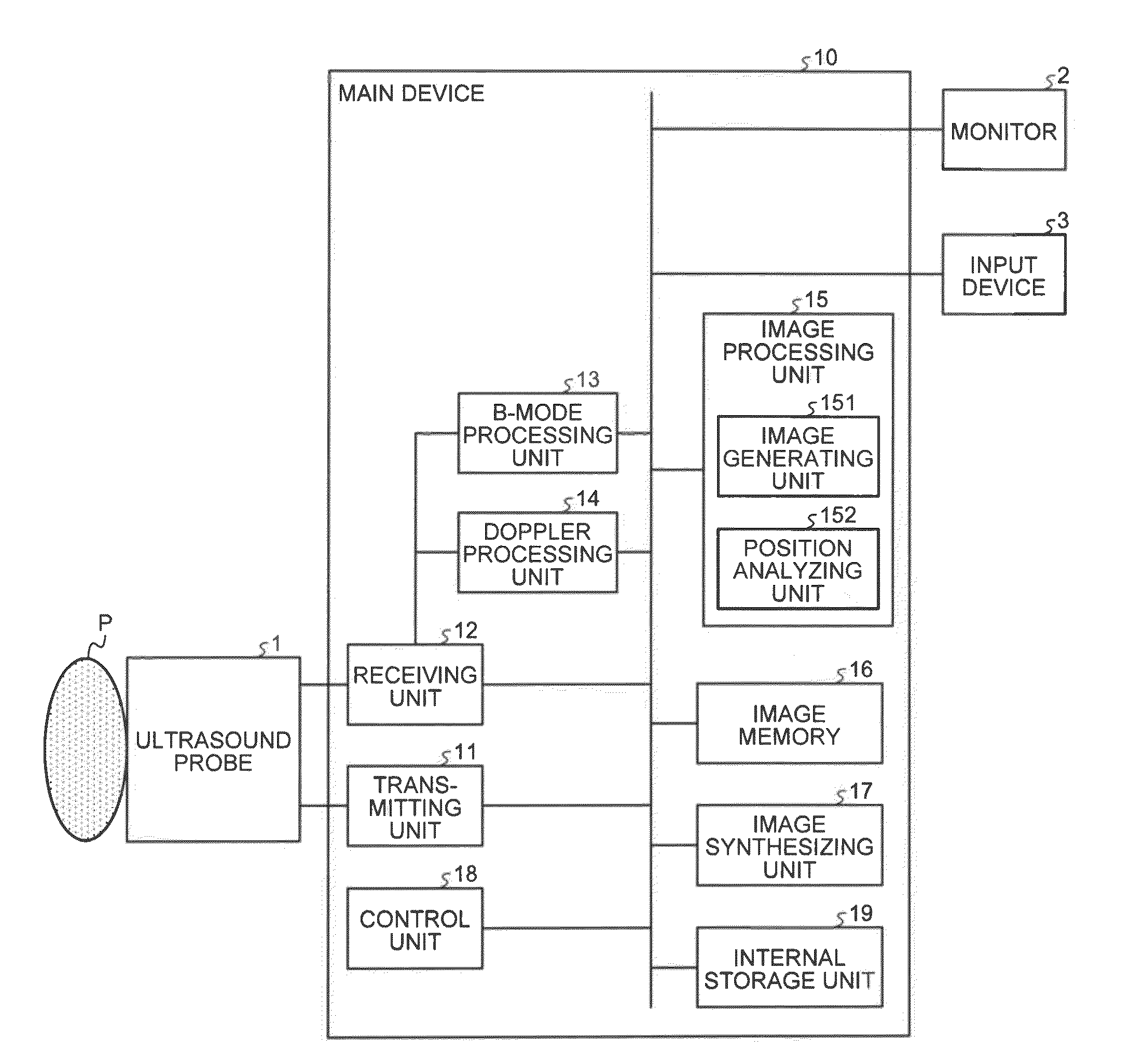
[0031]First, a configuration of an ultrasonic diagnostic apparatus according to the present embodiment is explained. FIG. 1 is a diagram for explaining a configuration of an ultrasonic diagnostic apparatus according to the present embodiment. As shown in FIG. 1, the ultrasonic diagnostic apparatus according to the present embodiment includes an ultrasound probe 1, a monitor 2, an input device 3, and a main device 10.

[0032]The ultrasound probe 1 includes an array of piezoelectric oscillators. These piezoelectric oscillators generate an ultrasound wave in accordance with a drive signal supplied from a transmitting unit 11 of the main device 10, which is described later, and also receives a wave reflected from a subject P and converts it to an electronic signal. ...


PUM


Abstract

The analysis image generating unit generates section images from volume analysis data that is collected by sending an ultrasound wave down to a region under the ribs. The right/left identifying unit identifies the right or left breast from cyclic motion components in the section images. The extending direction detecting unit analyzes plane-A images or plane-B images generated from the same volume analysis data, or a plane-C thickness-added MIP image, and detects the rib extending direction. The extending direction detecting unit also determines the position of the ultrasound probe based on the relative displacement of the extending direction. The body mark generating unit generates a body mark from the analysis results obtained by the right/left identifying unit and the extending direction detecting unit. The image synthesizing unit integrates the display image generated by the display image generating unit and the body mark, and displays it on the monitor.

Description

CROSS-REFERENCE TO RELATED APPLICATIONS[0001]This application is based upon and claims the benefit of priority from the prior Japanese Patent Application No. 2009-10246, filed on Jan. 20, 2009; the entire contents of which are incorporated herein by reference.BACKGROUND OF THE INVENTION[0002]1. Field of the Invention[0003]The present invention is related to an ultrasonic diagnostic apparatus, a positional information acquiring method, and a computer program product.[0004]2. Description of the Related Art[0005]Among conventional technologies, an ultrasonic diagnostic apparatus is advantageous in its operational ease and noninvasiveness without the possibility of exposure to radiation, to other medical diagnostic imaging devices such as an x-ray diagnostic device and an x-ray computer tomograph. The ultrasonic diagnostic apparatus is therefore widely used in examination and diagnosis of various parts of body tissues such as heart, liver, kidney, mammary gland, and muscles in today's m...

Claims


Application Information

Patent Timeline
Patent Type & Authority Applications(United States)
IPC IPC(8): A61B8/14
CPCA61B8/0825A61B8/14A61B8/463A61B8/5223A61B8/54
Inventor YAO, CONGKAMIYAMA, NAOHISAOKAMURA, YOKO
Owner TOSHIBA MEDICAL SYST CORP
Why Eureka
Try Eureka