Cannulated suture anchor

a cannula and anchor technology, applied in the field of cannulae, can solve problems such as weak fixation

Active Publication Date: 2010-07-22
DEPUY MITEK INC
View PDF99 Cites 59 Cited by
  • Summary
  • Abstract
  • Description
  • Claims
  • Application Information

AI Technical Summary

Benefits of technology

[0018]In other aspects, a method for anchoring suture to bone is provided and includes coupling a wire to a suture anchor such that the wire extends around a suture-engaging member extending across opposed sidewalls of an inner lumen of the suture anchor and first and second terminal ends of the wire extend through the inner lumen of the suture anchor, inserting the suture anchor into bone, and pulling the first terminal end of the wire to pull at least one suture strand coupled to the second terminal end of the wire through the inner lumen of the suture anchor and around the suture-engaging member. In one embodiment, the wire can be coupled to first and second suture strands such that pulling the first terminal end of the wire pulls the first and second suture strands through the inner lumen of the suture anchor and around the suture-engaging member. Alternatively, the wire can be coupled to a driver that is inserted into the inner lumen of the suture anchor, and that is actuated to drive the suture anchor into bone. Removing the driver from the suture anchor can be effective to pull the wires. The method can also include injecting a material through the inner lumen of the driver and into the inner lumen of the suture anchor. The material can be, for example, a bone-growth promoting material, a sealant, an adhesive, and combinations thereof. The method can also include attaching the suture(s) to tissue to anchor the tissue to the bone.

Problems solved by technology

Such injuries are generally the result of excessive stresses being placed on these tissues.
While current suture anchors are effective in anchoring soft tissue to bone, one drawback with current devices is that the suture anchor must have a head with a length that is sufficient to withstand a torque applied thereto by a driver.
Once implanted, tension applied to the anchor via the sutures can cause the anchor to migrate into the cortical bone and thus the head of the suture anchor can become proud, resulting in a weak fixation among other problems.

Method used


Image

  • Cannulated suture anchor
  • Cannulated suture anchor
  • Cannulated suture anchor

Examples


Embodiment Construction

[0044]Certain exemplary embodiments will now be described to provide an overall understanding of the principles of the structure, function, manufacture, and use of the devices and methods disclosed herein. One or more examples of these embodiments are illustrated in the accompanying drawings. Those of ordinary skill in the art will understand that the devices and methods specifically described herein and illustrated in the accompanying drawings are non-limiting exemplary embodiments and that the scope of the present invention is defined solely by the claims. The features illustrated or described in connection with one exemplary embodiment may be combined with the features of other embodiments. Such modifications and variations are intended to be included within the scope of the present invention.

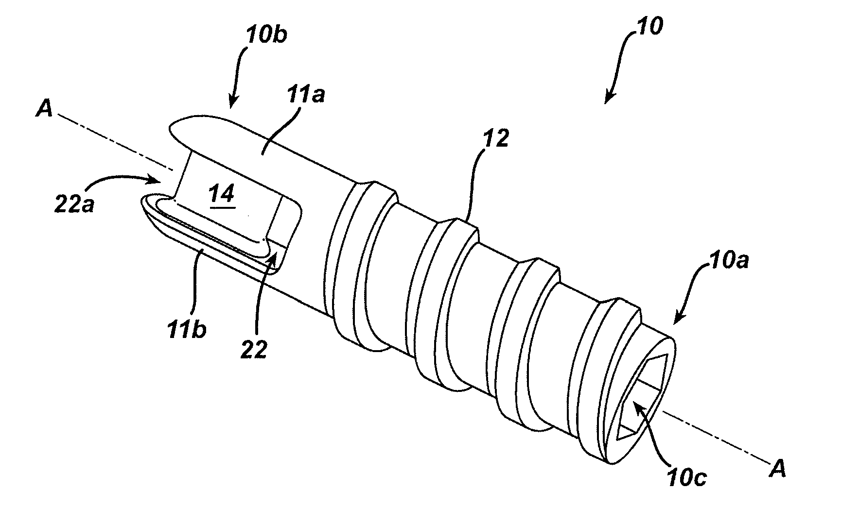
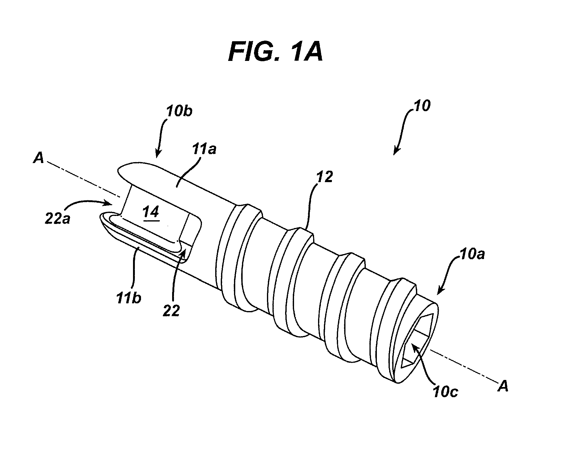
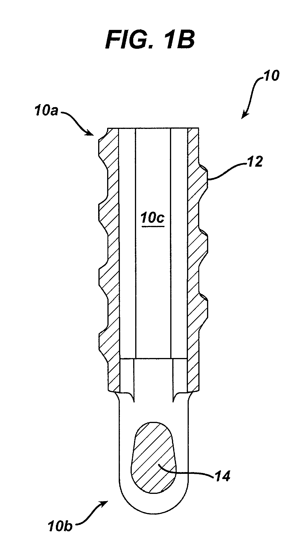
[0045]The present invention generally provides methods and devices for anchoring suture to bone. In an exemplary embodiment, a cannulated suture anchor is provided and it includes a suture-e...


PUM


Abstract

Methods and devices are provided for anchoring suture to bone. In one exemplary embodiment, a cannulated suture anchor is provided and it includes a suture-engaging member formed therein and configured to receive a suture therearound such that trailing ends of the suture can extend through the suture anchor. The present invention also provides exemplary sutures and drivers that can be used with the various methods and devices disclosed herein, or with other methods and devices known in the art.

Description

CROSS REFERENCE TO RELATED APPLICATIONS[0001]The present application is a divisional of U.S. application Ser. No. 11 / 555,545 filed on Nov. 1, 2006 and entitled “Cannulated Suture Anchor,” which is hereby incorporated by reference in its entirety.FIELD OF THE INVENTION[0002]The present invention relates generally to medical devices and procedures, and more particularly to systems and methods for attaching soft tissue to bone.BACKGROUND OF THE INVENTION[0003]The complete or partial detachment of ligaments, tendons and / or other soft tissues from their associated bones within the body are relatively commonplace injuries, particularly among athletes. Such injuries are generally the result of excessive stresses being placed on these tissues. By way of example, tissue detachment may occur as the result of an accident such as a fall, over-exertion during a work-related activity, during the course of an athletic event, or in any one of many other situations and / or activities.[0004]In the cas...

Claims


Application Information

Patent Timeline
Patent Type & Authority Applications(United States)
IPC IPC(8): A61B17/04
CPCA61B17/0401A61B17/0487A61B17/06166A61B17/888A61B2017/0403A61B2017/0409A61B2017/0412A61B2017/0414A61B2017/0427A61B2017/044A61B2017/0454A61B2017/0458A61B2017/0459A61B2017/0496A61B2017/0619A61B2017/0445
Inventor CAULDWELL, NATHANHOWE, JONATHANWOLF, EUGENE
Owner DEPUY MITEK INC
Why Eureka
Try Eureka