
Knotless instability anchor

a technology of anchors and knots, applied in the field of knotless anchors, can solve the problems of suture and soft tissue attached thereto slipping or otherwise moving, suture and soft tissue cannot be adjusted, and the soft tissue may not be in the optimal position to facilitate healing

Active Publication Date: 2016-02-23
MEDOS INT SARL
View PDF12 Cites 6 Cited by
  • Summary
  • Abstract
  • Description
  • Claims
  • Application Information

AI Technical Summary

Benefits of technology

The patent text describes a method to pull tissue closer to a bone hole using a suture anchor. This is done by applying tension to the suture anchor, which guides the tissue towards the bone hole. A guide member on a driver is used to keep the suture aligned with the anchor and free of the bone-engaging surface features. The technical effect of this method is improved tissue pullback during surgery, making it easier to securely attach tissue to the bone.

Problems solved by technology

Such injuries are generally the result of excessive stresses being placed on these tissues.
While current suture anchors are effective in anchoring soft tissue to bone, one drawback with current devices is that the suture and soft tissue attached thereto can slip or otherwise move while the suture anchor is being driven into the bone.
Once the suture anchor has been driven into bone, the suture and the soft tissue cannot be adjusted to adjust the position of the soft tissue relative to the bone because the driven suture anchor holds the suture and soft tissue in place.
The soft tissue may therefore not be in an optimal position to facilitate healing.
Even if the suture and the soft tissue can be adjusted after the suture anchor has been driven into bone, tying the suture into a knot can cause the soft tissue to slip from an optimal position.
Another drawback with current devices is that the suture anchor must have a head with a length that is sufficient to withstand a torque applied thereto by a driver.
Once implanted, tension applied to the anchor via the sutures can cause the anchor to migrate into the cortical bone and thus the head of the suture anchor can become proud, resulting in a weak fixation among other problems.

Method used


Image

  • Knotless instability anchor
  • Knotless instability anchor
  • Knotless instability anchor

Examples


Embodiment Construction

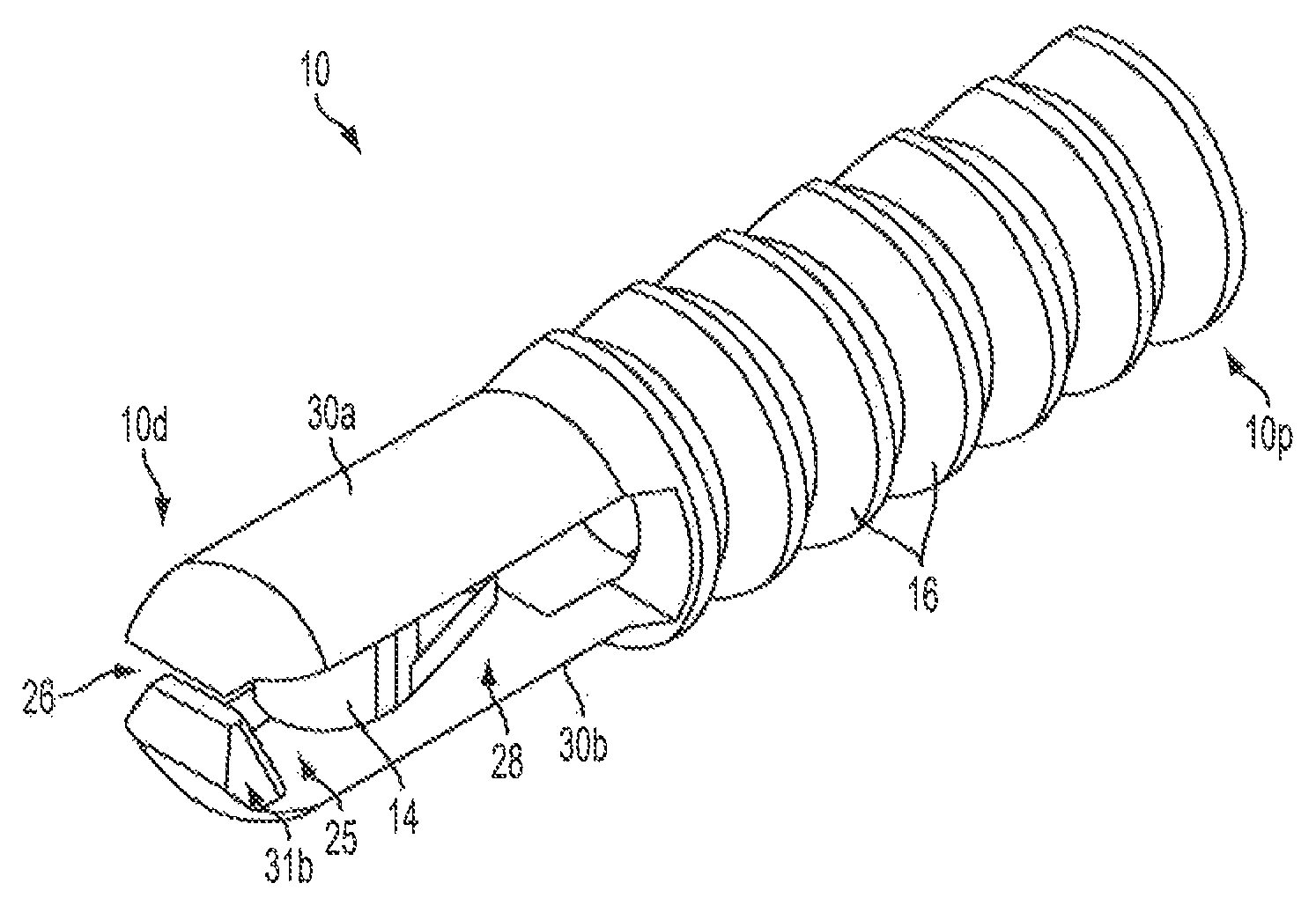
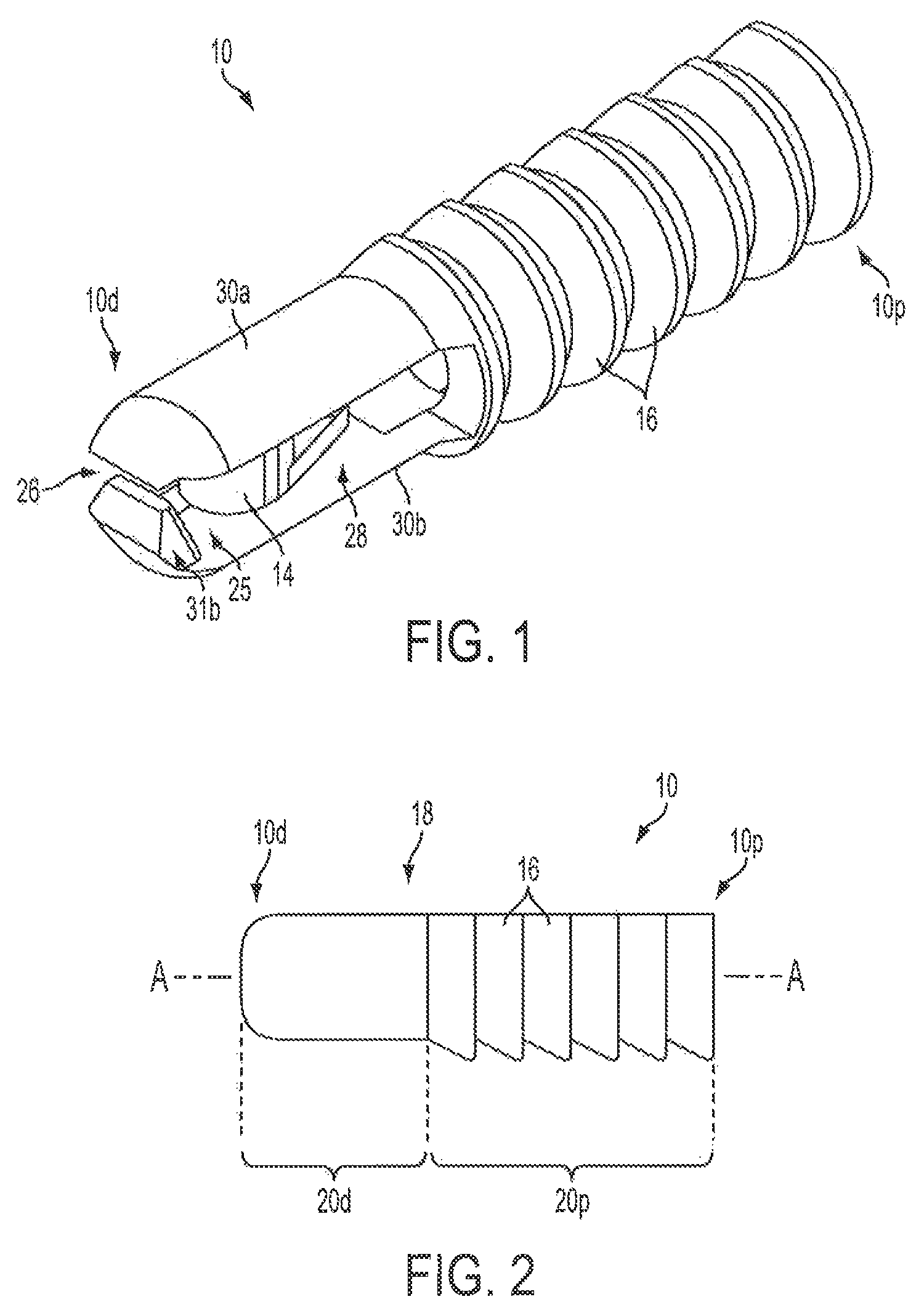
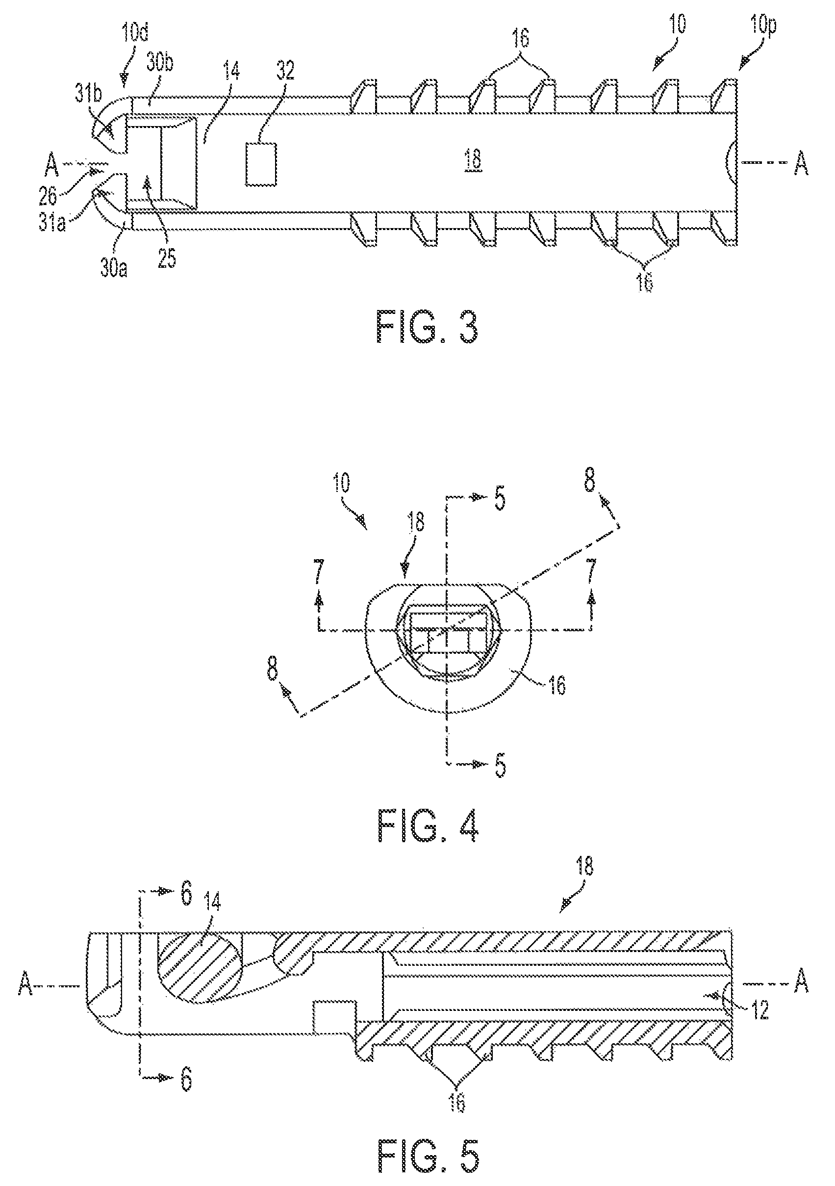
[0048]Certain exemplary embodiments will now be described to provide an overall understanding of the principles of the structure, function, manufacture, and use of the devices and methods disclosed herein. One or more examples of these embodiments are illustrated in the accompanying drawings. Those of ordinary skill in the art will understand that the devices and methods specifically described herein and illustrated in the accompanying drawings are non-limiting exemplary embodiments and that the scope of the present invention is defined solely by the claims. The features illustrated or described in connection with one exemplary embodiment may be combined with the features of other embodiments. Such modifications and variations are intended to be included within the scope of the present invention.

[0049]Various exemplary methods and devices are provided for anchoring soft tissue to bone. In general, the methods and devices can allow soft tissue to be secured to bone using a suture cou...


PUM


Abstract

Methods and devices are provided for anchoring suture to bone. In one exemplary embodiment, a suture anchor is provided that includes one or more bone-engaging surfaces features and an external sidewall. The external sidewall can allow a suture coupled to the suture anchor and located between the anchor and bone to be movable relative to the suture anchor, even when the suture anchor is partially or fully disposed within a bone hole. Suture threaders and suture anchor drivers are also provided that can be used with the various methods and devices disclosed herein, or with other methods and devices known in the art.

Description

FIELD OF THE INVENTION[0001]The present invention relates generally to methods and devices for anchoring soft tissue to bone, and in particular to knotless suture anchors and methods for use.BACKGROUND OF THE INVENTION[0002]The complete or partial detachment of ligaments, tendons, and / or other soft tissues from their associated bones within the body are relatively commonplace injuries, particularly among athletes. Such injuries are generally the result of excessive stresses being placed on these tissues. By way of example, tissue detachment may occur as the result of an accident such as a fall, over-exertion during a work-related activity, during the course of an athletic event, or in any one of many other situations and / or activities.[0003]In the case of a partial detachment, the injury will frequently heal itself, if given sufficient time and if care is taken not to expose the injury to further undue stress. In the case of complete detachment, however, surgery may be needed to re-...

Claims


Application Information

Patent Timeline
Patent Type & Authority Patents(United States)
IPC IPC(8): A61B17/04
CPCA61B17/0401A61B2017/0409A61B2017/0412A61B2017/0427A61B2017/0438A61B2017/0445A61B2017/0414
Inventor HESTER, DOUGLASOTRANDO, BRIAN
Owner MEDOS INT SARL
Learn More