
System and method for installing sheet piles

a sheet pile and installation apparatus technology, applied in mining structures, construction, foundation engineering, etc., can solve the problems of increasing the cost of sheet piles, increasing the cost of handling heavy piles, and increasing the bending strength, so as to reduce the risk of warpage or other deformation of sheet piles during installation, and effectively pull sheet piles into the ground

Active Publication Date: 2013-04-16
CMI CO LTD
View PDF24 Cites 8 Cited by
  • Summary
  • Abstract
  • Description
  • Claims
  • Application Information

AI Technical Summary

Benefits of technology

The present invention is an improved system and method for installing sheet piles and other barrier components into soil. The system and method provide a better way to pull the sheet piling into the ground, reducing warping or deformation during installation. The invention includes protective toe members, a grout tube for sealing between piling members, and a tandem or plural pile installation system and method. The technical effects include improved efficiency and accuracy in the installation of sheet piles and other barrier components.

Problems solved by technology

The additional material used in “over-sizing” increases the costs of the sheet piles due to the material itself, as well as the costs associated with handling the heavier piles.
The increased bending strength does not offset the cost of the additional plastic.
As previously noted, although measures can be taken to increase the ability of extruded plastic sheet piles to withstand the large axial loads applied during driving operations, it is not uncommon to damage sheet piles during driving operations.
Miscalculations and / or misjudgments related to the required thickness of the sheet piles, or simple over application of driving force, can cause the sheet piles to be damaged.
Removal and replacement of the damaged sheet piles is costly in both time and materials.
As well, warpage, twisting, deflection, etc., of a structural panel during driving operations can cause the male and female locked edges to separate between adjacent sheet piles.
If the separation goes undetected, the structural integrity of the barrier wall can be severely compromised.
This is especially harmful where the barrier wall is being used to prevent the spread of potentially harmful liquids, such as when used on industrial facilities, around garbage dumps, during the clean up of polluted areas, etc.

Method used


Image

  • System and method for installing sheet piles
  • System and method for installing sheet piles
  • System and method for installing sheet piles

Examples


Embodiment Construction

[0037]The present invention may be understood more readily by reference to the following detailed description of the invention taken in connection with the accompanying drawing figures, which form a part of this disclosure. It is to be understood that this invention is not limited to the specific devices, methods, conditions or parameters described and / or shown herein, and that the terminology used herein is for the purpose of describing particular embodiments by way of example only and is not intended to be limiting of the claimed invention. Any and all patents and other publications identified in this specification are incorporated by reference as though fully set forth herein.

[0038]Also, as used in the specification including the appended claims, the singular forms “a,”“an,” and “the” include the plural, and reference to a particular numerical value includes at least that particular value, unless the context clearly dictates otherwise. Ranges may be expressed herein as from “abou...


PUM


Abstract

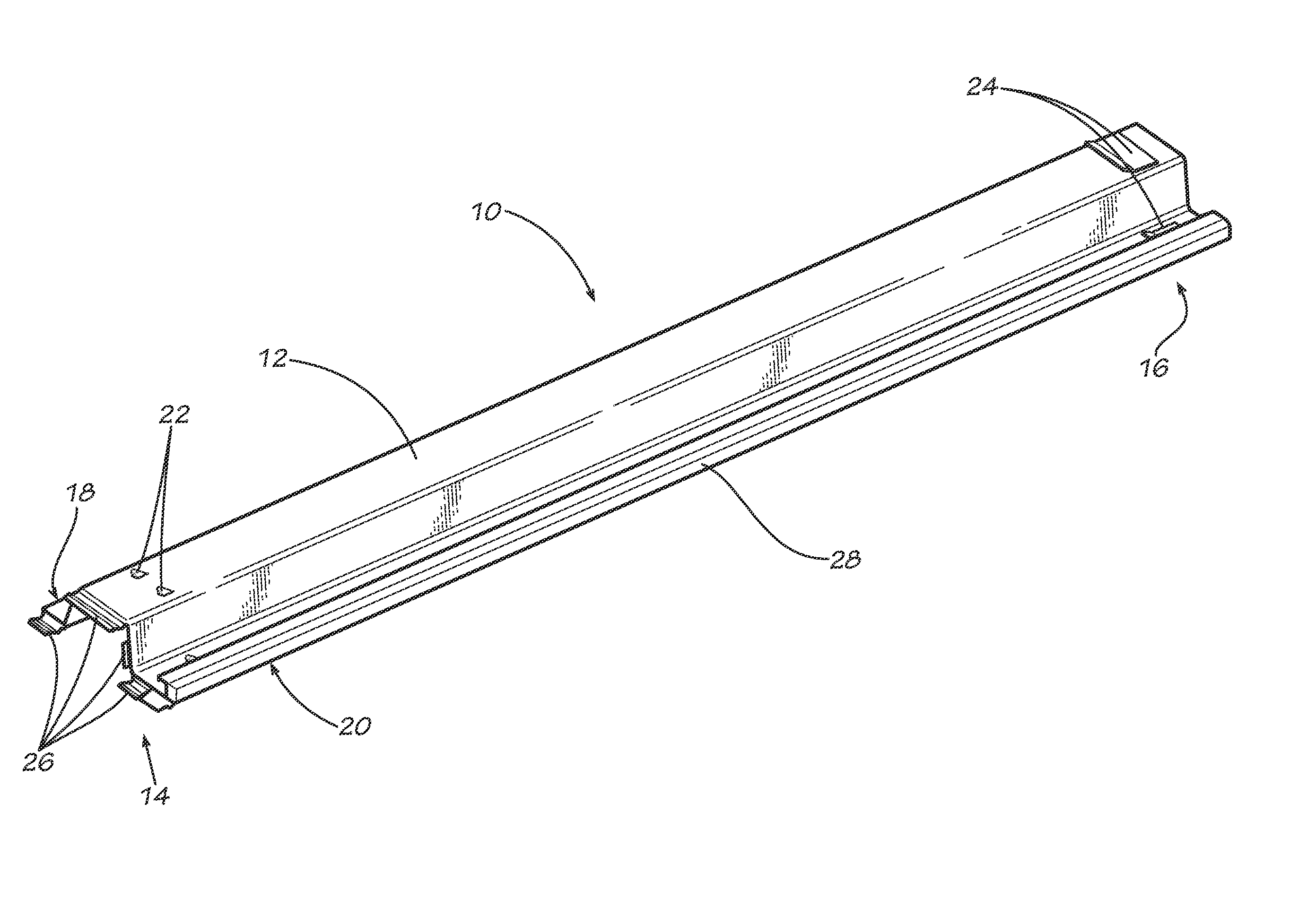
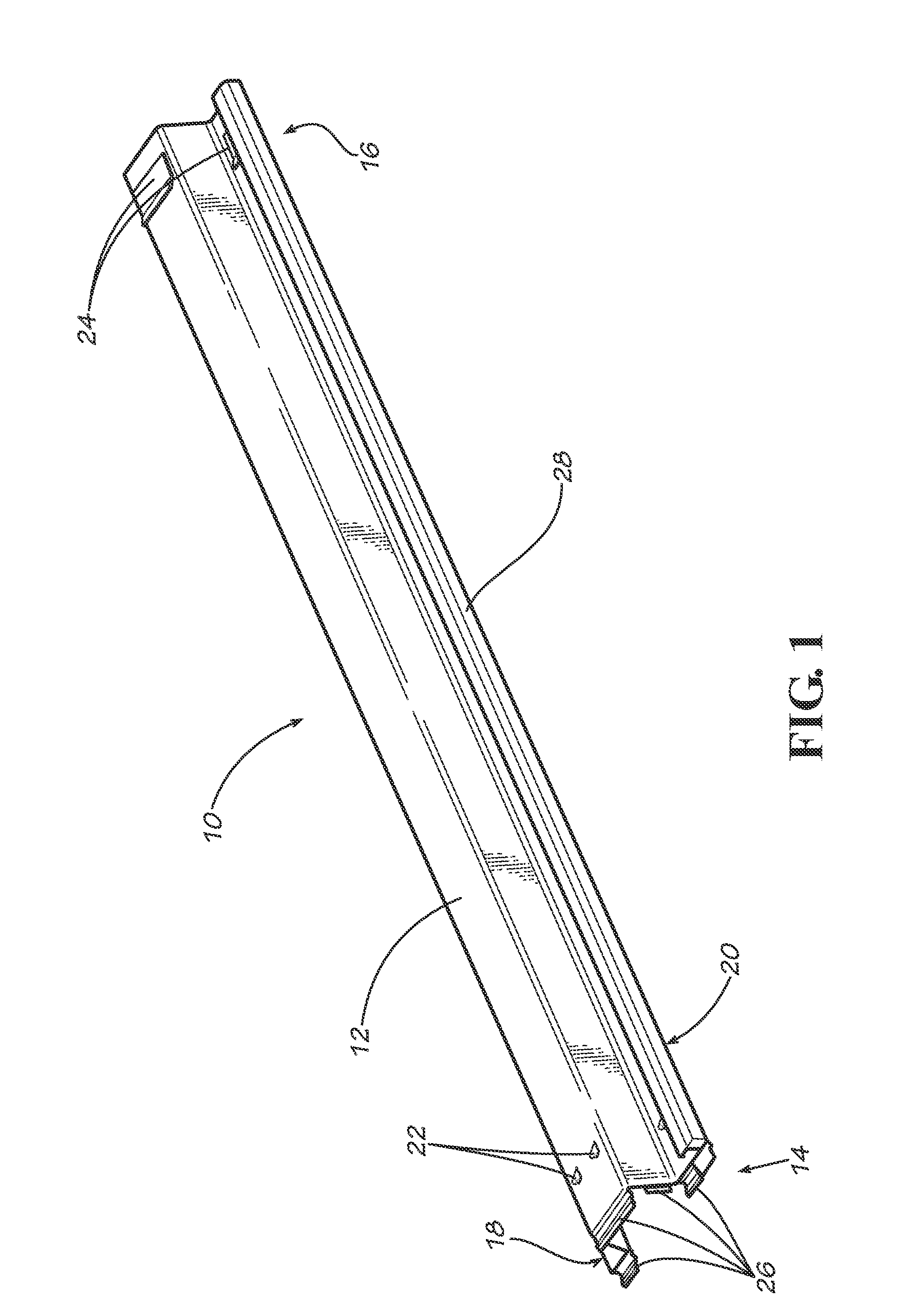
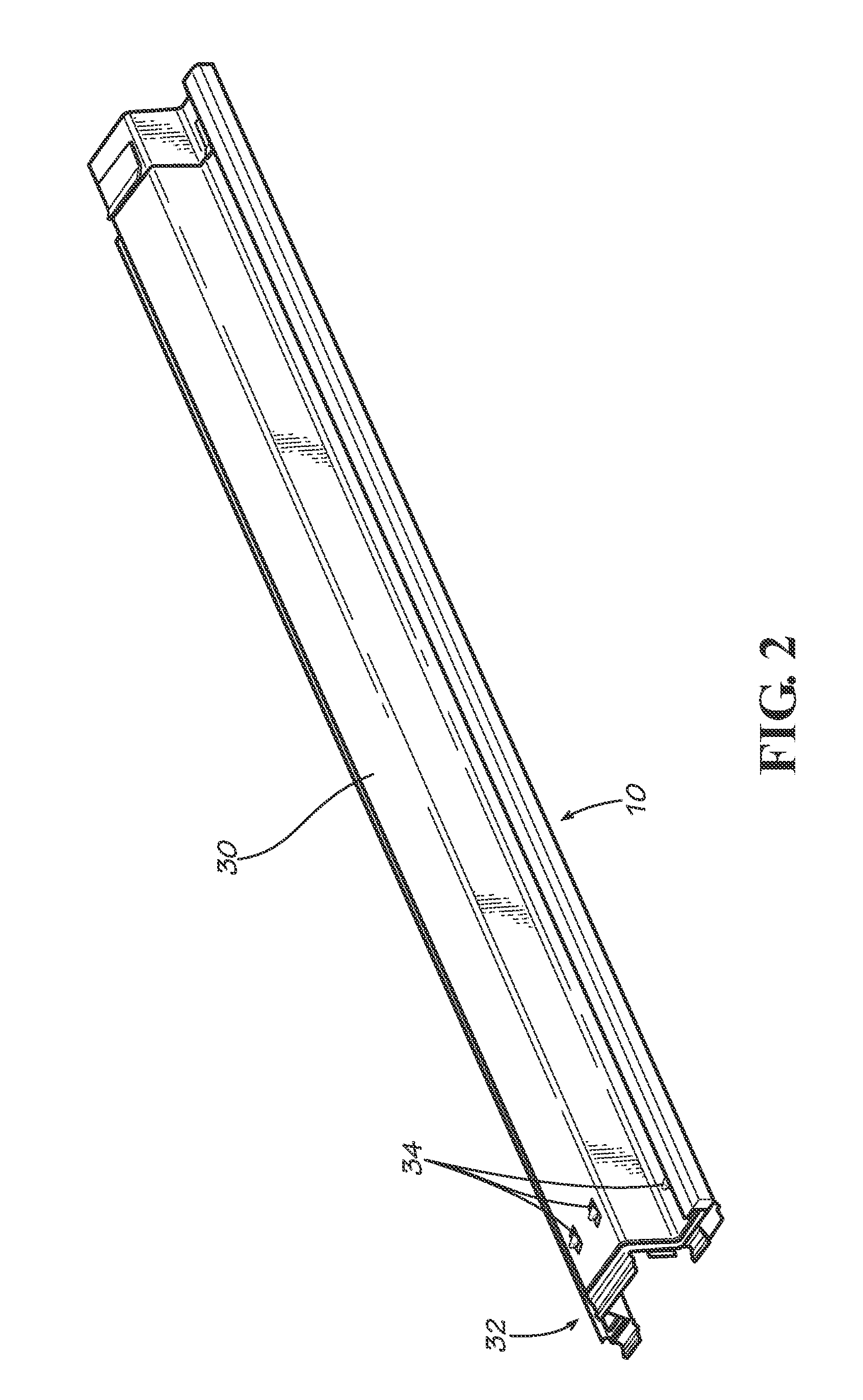
A system for installation of sheet pile including a sheet pile installation apparatus having a substantially rigid elongate beam with an upper end and a lower end, and at least one drive finger proximal the lower end of the substantially rigid elongate beam; and a sheet pile having an elongate member with an upper end and a lower end, and a first side and a second side, the first side having a male profile lock and the second side having a female profile lock, the sheet pile further including at least one receiver proximal the lower end for receiving the at least one drive finger of the sheet pile installation apparatus.

Description

CROSS-REFERENCE TO RELATED APPLICATION[0001]This application claims priority benefit to U.S. Provisional Patent Application Ser. No. 61 / 177,536 filed May 12, 2009 and U.S. Provisional Patent Application Ser. No. 61 / 225,444 filed Jul. 14, 2009, which are hereby incorporated herein by reference.TECHNICAL FIELD[0002]The present disclosure relates generally to methods and apparatuses for use in forming driven wall structures constructed of structural panels such as sea walls, retaining walls, dikes, barrier walls and the like. More specifically, the present disclosure relates to a sheet pile system and a sheet pile installation apparatus for inserting sheet piles vertically into soil formations, and methods of use thereof.BACKGROUND[0003]Barrier walls that are formed from a plurality of elongated, vertically oriented piles typically are driven into the earth to a depth sufficient to support the piles in an upright attitude. In some cases, the piles are formed with male and female oppose...

Claims


Application Information

Patent Timeline
Patent Type & Authority Patents(United States)
IPC IPC(8): E02D5/16
CPCE02D5/02E02D7/02E02D11/00E02D13/00E02D13/04
Inventor IRVINE, JOHN E.HARGRAVE, STEVEN E.BROWN, CHARLES B.
Owner CMI CO LTD
Learn More