Eureka AIR delivers breakthrough ideas for toughest innovation challenges, trusted by R&D personnel around the world.

Automatic mapping and updating computer switching device

a computer and switching device technology, applied in computing, instruments, electric digital data processing, etc., can solve the problems of incompatibility and disconnection of multi-function mouse, keyboard, joystick, touch screen or other usb human interface device (hidden) with the computer, and the inability to satisfy all usb devices, etc., to improve the convenience of operation and enhance the safety

Inactive Publication Date: 2010-07-22
JUNE ON
View PDF6 Cites 16 Cited by
  • Summary
  • Abstract
  • Description
  • Claims
  • Application Information

AI Technical Summary

Benefits of technology

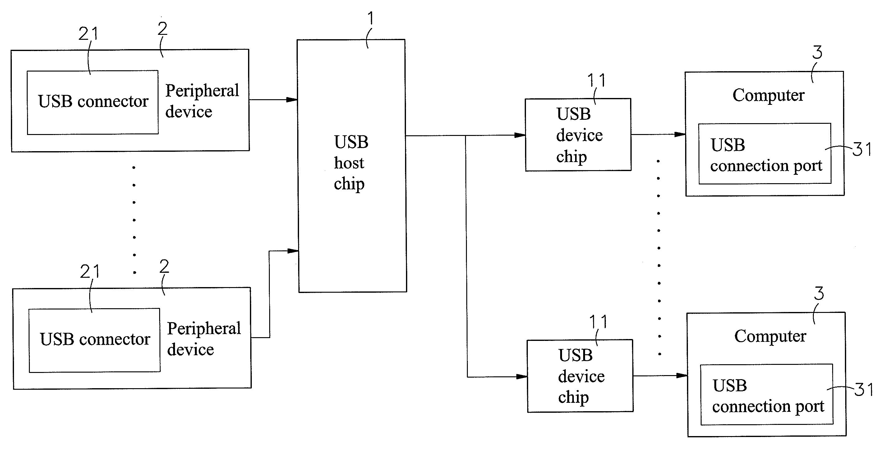
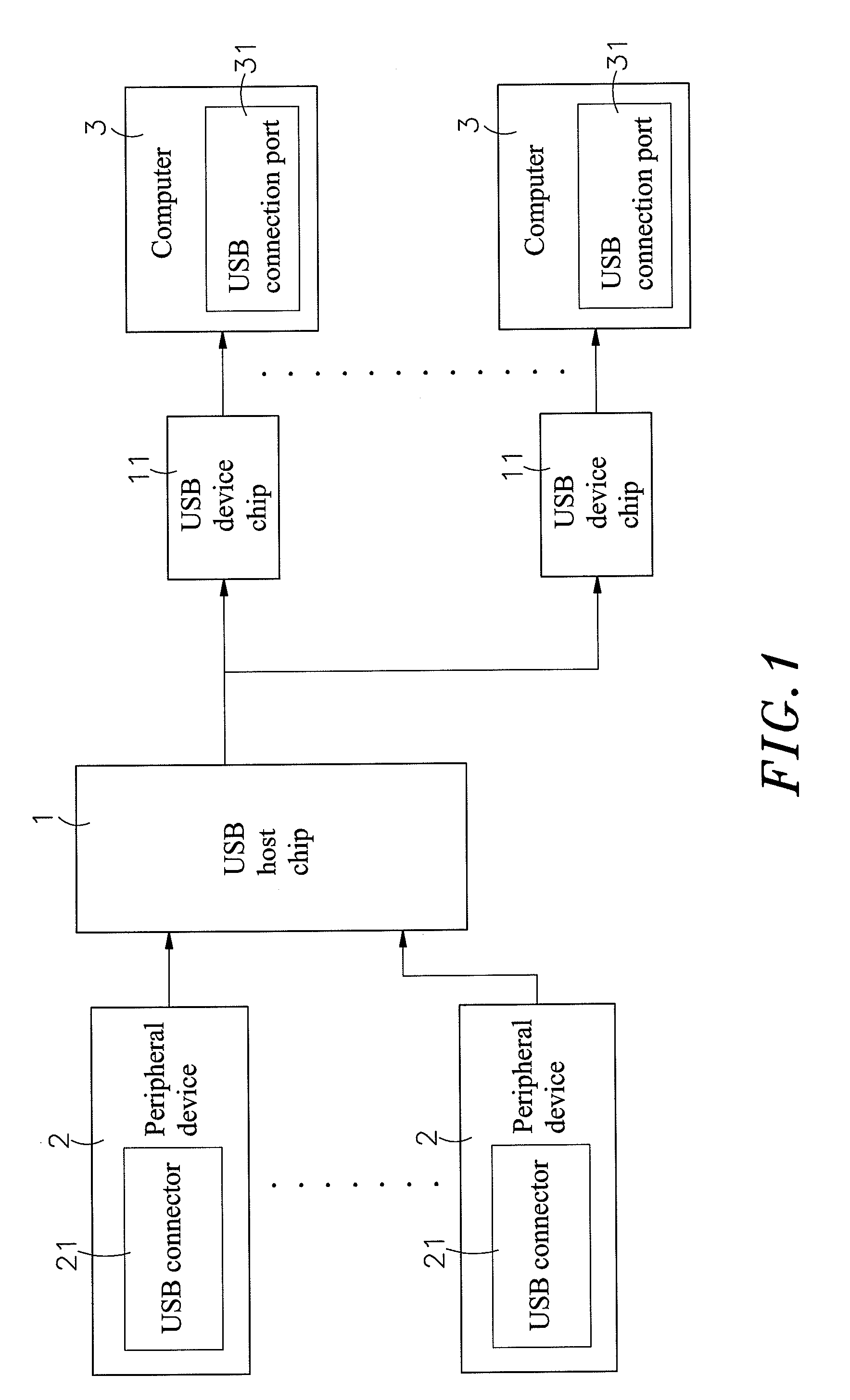
[0009]The present invention has been accomplished under the circumstances in view. It is therefore one object of the present invention to provide an automatic mapping and updating computer switching device which comprises a USB Host Chip connected to a plurality of peripheral device each containing a USB connector. The USB Host Chip can read the necessary data of the peripheral devices, or monitors and records the necessary data (USB device descriptor / report) while the necessary data of the peripheral devices are transmitted to the computers by a USB switch chip via a USB hub chip in order to gain and store the descriptors and necessary data including report analysis, enumeration, type or form, of the peripheral devices, then these necessary data are sent to a plurality of USB Device Chips for storage. Such that, when the computers communicate with the connected USB Device Chips, the USB Device Chips send the stored necessary data to the computers and enable the peripheral devices to perform the operations to the computers, and further, the computability between the peripheral devices and the computers is guaranteed.
[0011]A further object of the present invention is to enable the memory in the USB host chip to store the limitations set by the administrator, which consist of the necessary data (USB device descriptors) of the peripheral devices, so that the USB host chip can transmit the necessary data to multiple USB device chips to enable connection of the peripheral devices with the computer only after the peripheral devices that meet the requirements for device type, brand, name or model as set in the limitations are connected. By doing so, only peripheral devices of the identified users are allowed to be connected to the computer, while other peripherals cannot be connected, thus achieving enhanced safety and improved operating convenience.

Problems solved by technology

But under the situations of limited space or budgets, these ideas often never come true.
However, since a USB-type computer switch available on the market is impossibly applied to all type of USB devices, it often leads to incompatibility and disconnection of the multi-function mouse, keyboard, joystick, touch screen or other USB human interface device (HID) with the computers.
The devices enumeration, descriptors report analysis or other structural configuration of the USB-type computer switch are stimulated and converted to an established computer interface format, therefore, it cannot satisfy all USB devices.
But the two methods cannot resolve the incompatibility problem completely.
But due to wide-spread use of portable storage devices, these data and documents are subject to theft and disclosure; therefore, these companies disable, seal or remove USB ports of the computers in succession to prevent any disclosure.
Under such circumstances, however, users will be confronted with operating difficulties when they need to gain access to these data or documents or connect to a certain peripheral (such as a printer or scanner).
If the computer switch is used, it is impossible to disable, seal or remove USB ports.
As a result, the confidential data and documents of the companies are very liable to theft or disclosure.

Method used


Image

  • Automatic mapping and updating computer switching device
  • Automatic mapping and updating computer switching device
  • Automatic mapping and updating computer switching device

Examples


Embodiment Construction

[0017]Referring to FIG. 1, an automatic mapping and updating computer switching device in accordance with the present invention is shown comprised of a USB Host Chip 1. The USB Host Chip 1 is provided for connecting with a plurality of peripheral devices 2 each containing a USB connector 21 and a plurality of USB Device Chips 11. The USB Device Chips 11 are further connected to a plurality of computers 3 each having a USB connection port 31.

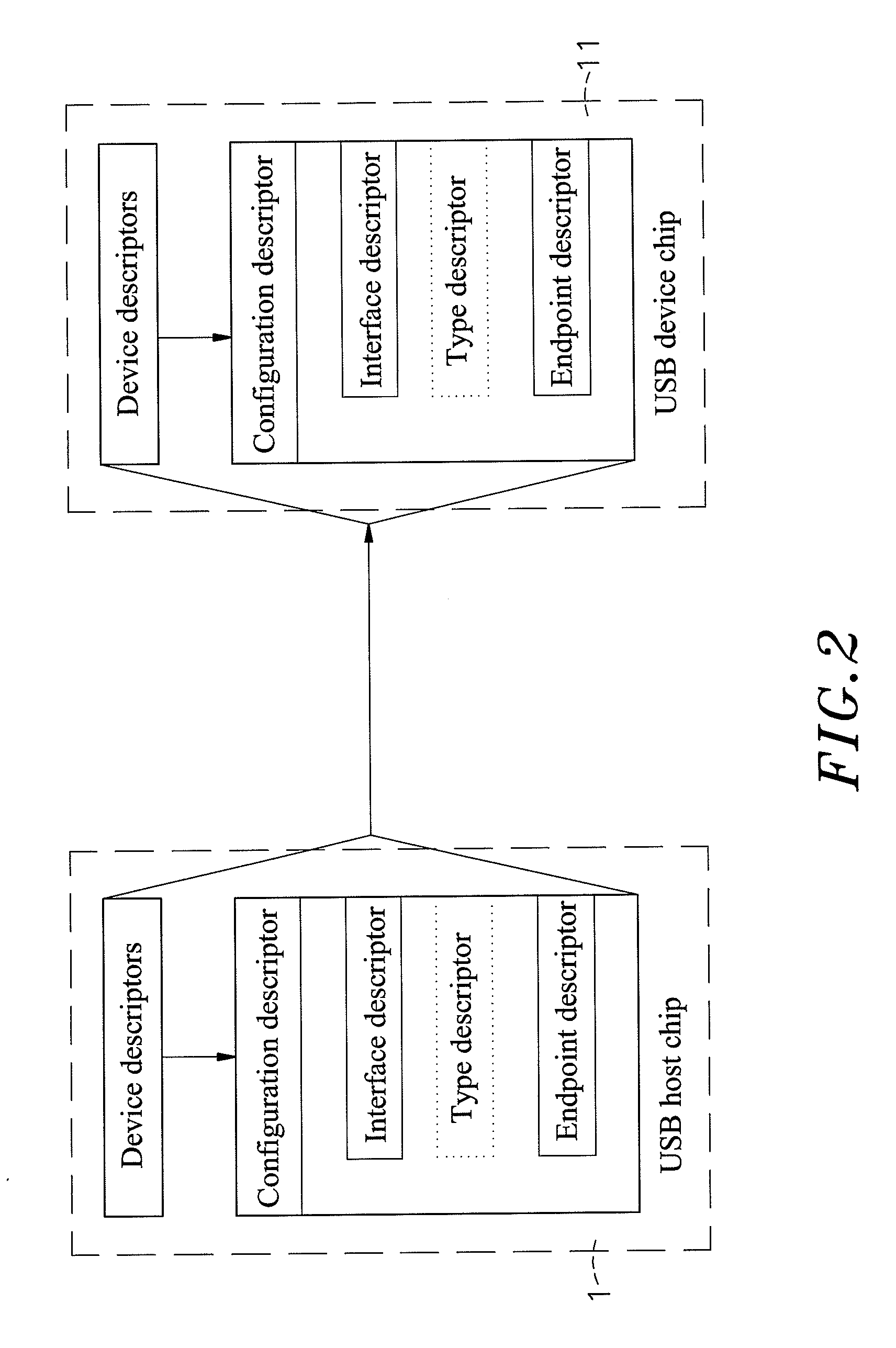
[0018]When in use, the USB Host Chip 1 is stimulated as a host and fully communicates with the peripheral devices 2 connected to the computer switching device based on the standard USB communication protocol to read and store the descriptors and necessary data including report analysis, enumeration, type or form, of the peripheral devices 2, wherein the descriptors include the configuration descriptor, interface descriptor, class descriptor and endpoint descriptor. Then these necessary data are transmitted to the USB Device Chips 11 for storage, ...


PUM


Abstract

The present invention relates to an automatic mapping and updating computer switch device. The computer switching device provides the compatibility between a plurality of devices and a plurality of computers, and comprises a USB Host Chip connected to the plurality of peripheral devices each containing a USB connector for sending the necessary data (USB device descriptor / report) to a plurality of USB Device Chips, thus, the computers can acquire the necessary data of the peripheral devices through the connected USB Device Chips. Whenever the computer switching device re-boots or any of the peripheral devices are plugged in / pulled out, the USB Host Chip reads the new necessary data again with the previous ones, if any differences are found, the new necessary data is send to the USB Device Chip for storage.The aforesaid procedure is called DDM (Dynamic Devices Mapping) or full USB Enumeration or full USB Initiation.

Description

[0001]This application is a Continuation-In-Part of my patent application Ser. No. 12 / 060,879, filed on Apr. 2, 2008.BACKGROUND OF THE INVENTION[0002]1. Field of the Invention[0003]The present invention relates to an automatic mapping and updating computer switching device, particularly, to the computer switching device that ensures the compatibility between a plurality of peripheral devices and a plurality of computers.[0004]2. Description of the Related Art[0005]When a computer fails to meet the operational requirement, adding a new computer or continuing to use the old one is the most common solution. But under the situations of limited space or budgets, these ideas often never come true. However, thanks to the rapid development of electronics and information technology, two or more computers, whether new or old, can share one keyboard, mouse, monitor and even one speaker, microphone and any other peripheral devices simply through connecting in series to a computer switch (KVM). ...

Claims


Application Information

Patent Timeline
IPC IPC(8): G06F3/00G06F13/12
CPCG06F13/404
Inventor WU, HUNG-JUNECHOU, CHENG-SHENG
Owner JUNE ON
Why Eureka
Eureka Blog
Learn More