Lifting hook

a technology of lifting hooks and hooks, which is applied in the direction of load-engaging elements, transportation and packaging, etc., can solve the problems of serious damage, unusability, and the expensive reeling shaft of paper rolls being twisted and unusabl

Active Publication Date: 2010-07-29
KONECRANES GLOBAL
View PDF8 Cites 1 Cited by
  • Summary
  • Abstract
  • Description
  • Claims
  • Application Information

AI Technical Summary

Benefits of technology

[0011]The control power of the control device that guides the lifting hook to its position is produced by means of the driving movement of the crane, taking advantage of the shape of the mechanical control device to be described below, for simultaneously deviating the hook from its position of balance for guiding it to a lifting contact with the lifting surface.

Problems solved by technology

A problem with the paper roll handling described above is that particularly in connection with an automated lifting control, the lifting hook does not engage properly with the lifting surface groove, the hook drifts outside the groove or an erroneous hook locking confirmation is received even if locking of the hook to the proper locking point had not taken place.
If the paper roll or one of its ends then comes off from one or both of the hooks in connection with the lifting, serious damage may be caused.
Typically, if a roll falls onto its support stand from a height more than 10 cm, for example, the expensive reeling shaft of the paper roll will become twisted and unusable.
On the other hand, if the roll falls onto the floor of the paper mill, the entire floor structure may suffer significant damages on a large area.
Automated lifting control has typically been carried out using information provided by location sensors mounted to the lifting hook and possibly to the reeling shaft of the paper roll as well, which has not been completely reliable in all situations.
It is clear from the above that without reliable lifting hook control, fastening and locking paper rolls may be expected to fall off and to cause considerable costs due to damages.
If this risk is to be avoided, as it nowadays always is, the handling of paper rolls will suffer from unnecessary delays because of the obligatory manual and visual control checks made on foot.

Method used


Image

  • Lifting hook
  • Lifting hook
  • Lifting hook

Examples


Embodiment Construction

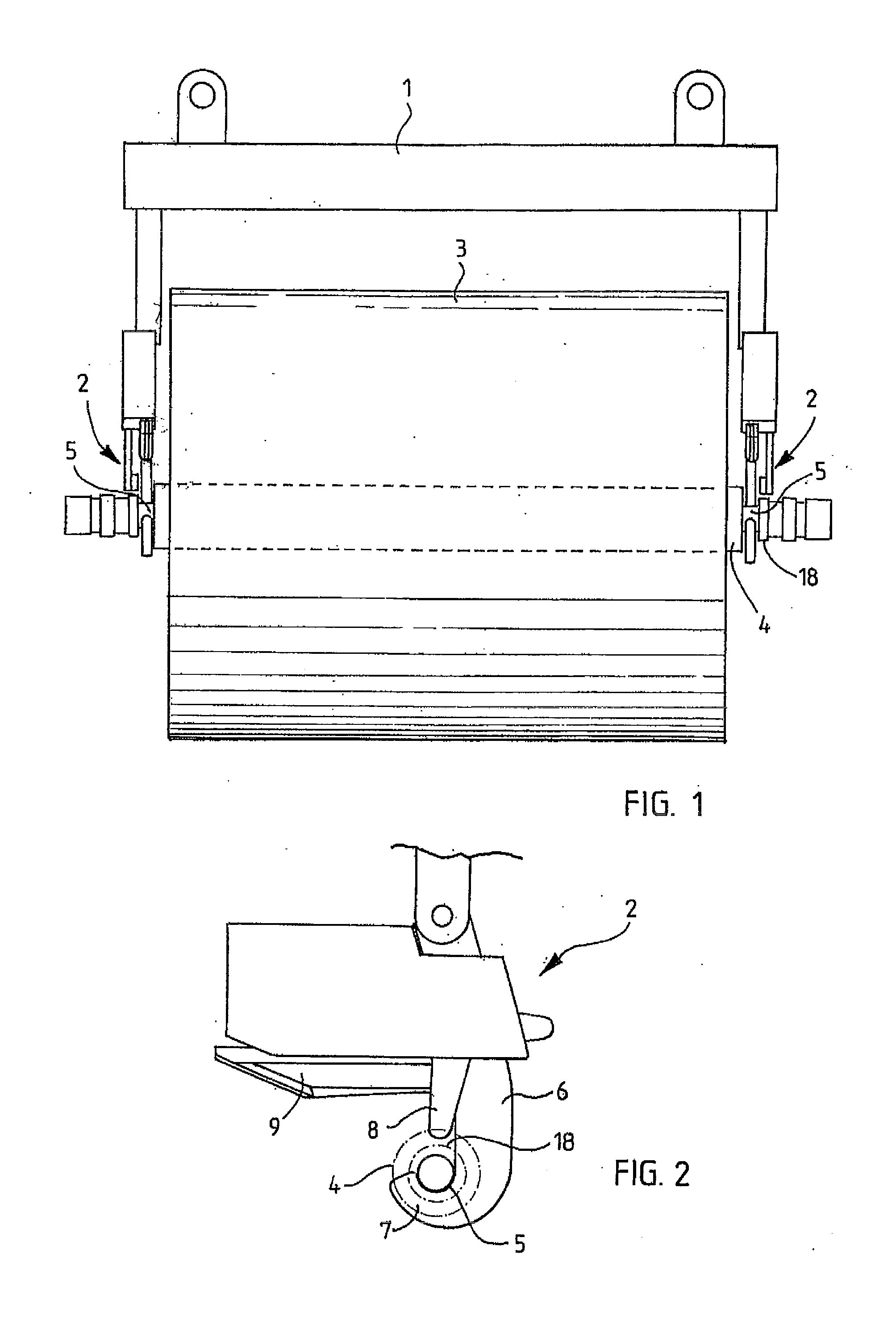
[0018]With reference FIG. 1, a load beam 1 of a crane bridge is shown, the ends of the beam being provided with lifting hooks 2 of the invention. The lifting hooks 2, in turn, are shown engaged with cylindrical lifting surface grooves 5 provided on a reeling shaft 4 of a jumbo paper roll 3 of a paper mill, the grooves having a diameter which is smaller than adjacent surface portions of the reeling shaft 4.

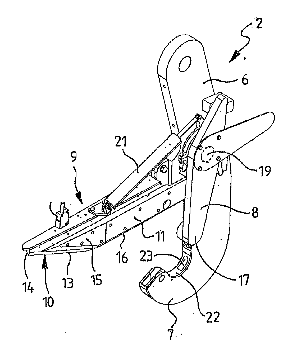
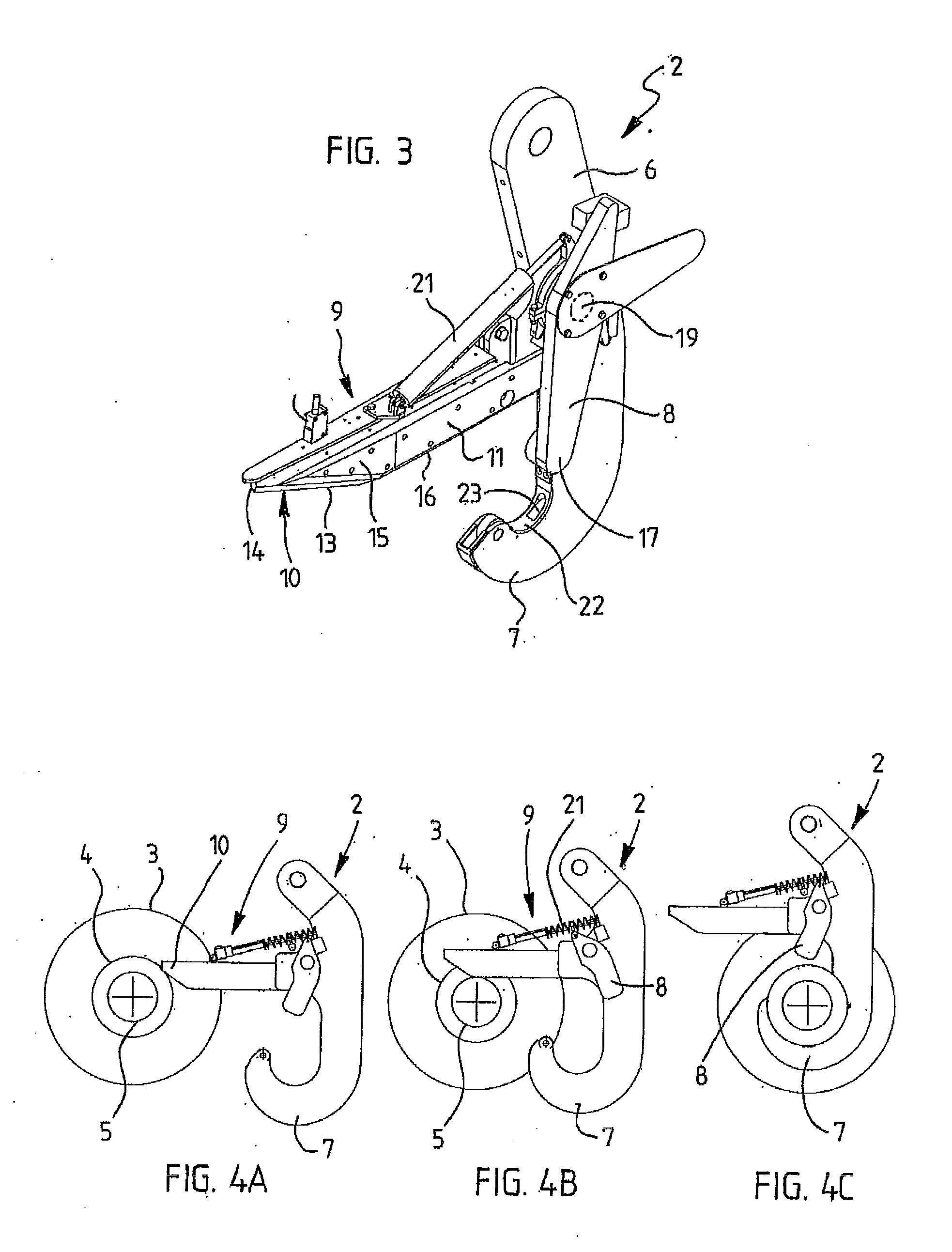
[0019]FIGS. 2 and 3 show a more detailed view of the lifting hook 2, which comprises a hook shank 6, a hook part 7 joining the hook shank 6, a locking device 8 arranged to lock the lifting hook to the object to be lifted, i.e. to the roll 3 in this case, a mechanical control device 9 mounted above the hook part 7 and arranged to co-operate with the upper surface of the lifting surface groove 5 for guiding the hook part 7 to a lifting position onto the lower surface of the lifting surface groove.

[0020]The control device 9 is a protrusion 9 which is narrower than the lifting surface ...


PUM

PropertyMeasurementUnit
heightaaaaaaaaaa
diameteraaaaaaaaaa
areaaaaaaaaaaa

Abstract

A lifting hook is arranged to grab an object to be lifted by a cylindrical lifting surface formed thereto, the lifting hook having a hook shank, a hook part joining the hook shank and a locking device arranged to lock the lifting hook to the object to be lifted. To allow the lifting hook to be reliably attached to the piece to be lifted, a mechanical control device is mounted above the hook part to co-operate with the upper surface of the lifting surface for guiding the hook part to a lifting position onto the lower surface of the lifting surface.

Description

BACKGROUND OF THE INVENTION[0001]The invention relates to a lifting hook arranged to grab an object to be lifted by a cylindrical lifting surface formed thereto, the lifting hook having a hook shank, a hook part joining the hook shank and a locking device arranged to lock the lifting hook to the object to be lifted, a mechanical control device being mounted above the hook part to co-operate with the upper surface of the lifting surface for guiding the hook part to a lifting position onto the lower surface of the lifting surface. The invention particularly relates to a hook meant for handling jumbo paper rolls in a paper mill, in which case two hooks are usually provided. The hooks are attached to the ends of a load-carrying beam designed for handling paper rolls and configured to engage with cylindrical lifting surfaces of cylindrical reeling shafts of the paper rolls. The hook is also suitable for handling other objects provided with a cylindrical lifting surface.[0002]Prior art li...

Claims


Application Information

Patent Timeline
Patent Type & Authority Applications(United States)
IPC IPC(8): B66C1/36B66C1/34
CPCB66C1/36B65H2301/41732B66C1/34
Inventor PIINSPANEN, HANNULEHTINEN, ARINIKKOLA, JARMOHYTONEN, KIMMO
Owner KONECRANES GLOBAL
Why Eureka
Try Eureka