
Systems and methods for graph-based pattern recognition technology applied to the automated identification of fingerprints

a fingerprint identification and graph-based pattern technology, applied in the field of graph-based pattern recognition technologies, can solve the problems of no scientific study that reasonably is conducted, no standard agreement among examiners, and current fingerprint analysis techniques are vulnerable to daubert challenge in the courts

Inactive Publication Date: 2010-07-29
GANNON TECH GROUP
View PDF38 Cites 35 Cited by
  • Summary
  • Abstract
  • Description
  • Claims
  • Application Information

AI Technical Summary

Benefits of technology

[0019]According to another aspect, a fingerprint recognition system for searching fingerprints in a source language comprises an imaged fingerprint, the imaged fingerprint being stored in a fingerprint database; a fingerprint library for storing fingerprint templates; an image graph constructor coupled to the fingerprint database and the template library, the image graph constructor configured to generate image graphs from the templates, and generate a collection of image graphs representing the imaged fingerprint by performing an image graph generation process, the process comprising the steps of: reducing fingerprint features in the templates and in the imaged fingerprint to skeleton images comprising a plurality of nodes and a plurality of connection...

Problems solved by technology

Current fingerprint analysis techniques are vulnerable to the Daubert challenge in the courts.
Yet, there appears to be no standard agreement among examiners as to which ridge characteristics are most indicative of identity.
No scientific study has been performed that reasonably indicates the probabilities of fingerprints from different people having varying numbers of matching ridge characteristics.
All prints, both inked and latent, are subject to various types of distortions and artifacts: The most common is pressure distortion.
Even though such distortions can cause a ridge characteristic to appear as something other than that, no study has been conducted to determine the frequency with which such distortions occur, and the extent to which such distortions can adversely impact identification.

Method used


Image

  • Systems and methods for graph-based pattern recognition technology applied to the automated identification of fingerprints
  • Systems and methods for graph-based pattern recognition technology applied to the automated identification of fingerprints
  • Systems and methods for graph-based pattern recognition technology applied to the automated identification of fingerprints

Examples


Embodiment Construction

.”

BRIEF DESCRIPTION OF THE DRAWINGS

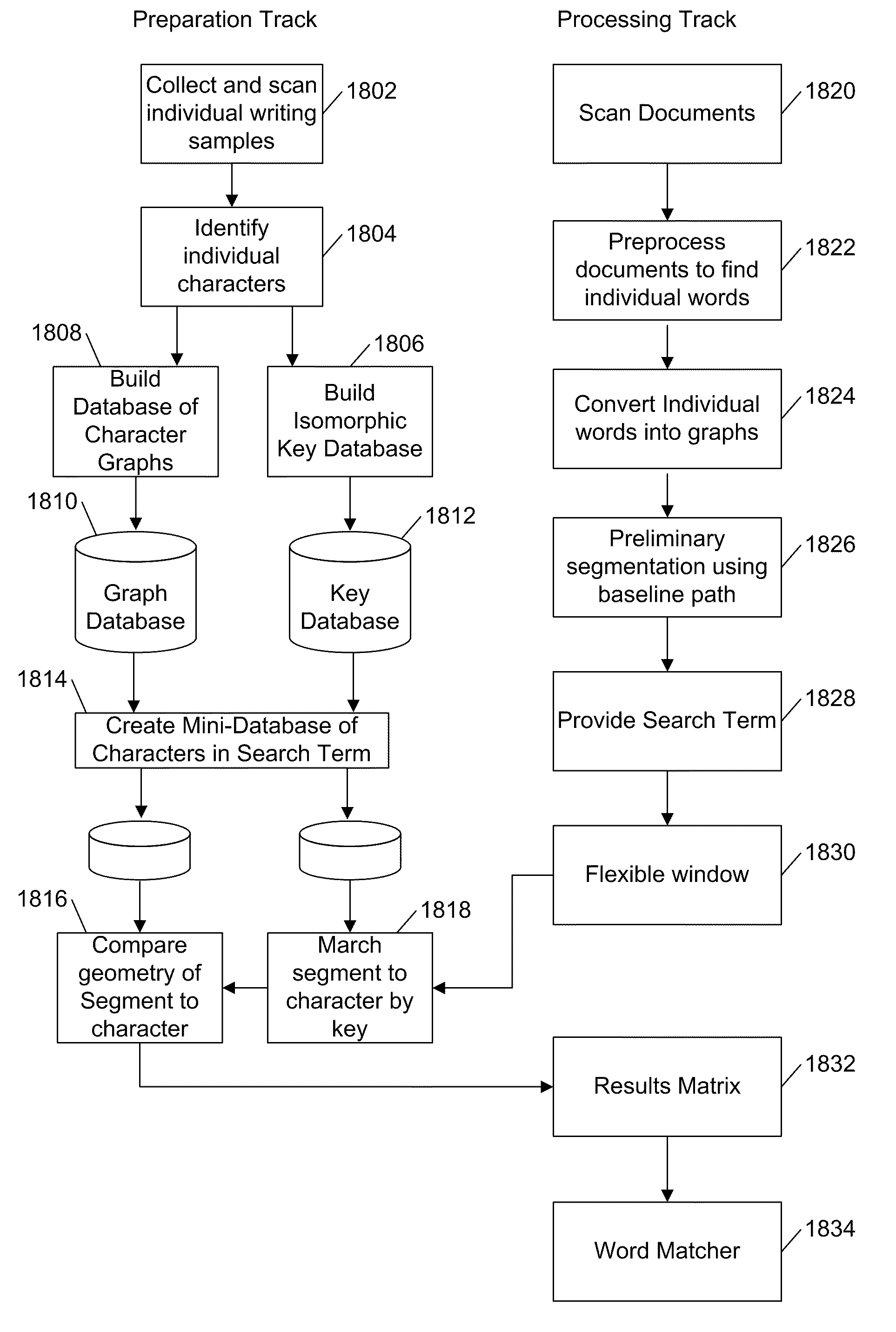
[0021]Features, aspects, and embodiments are described in conjunction with the attached drawings, in which:

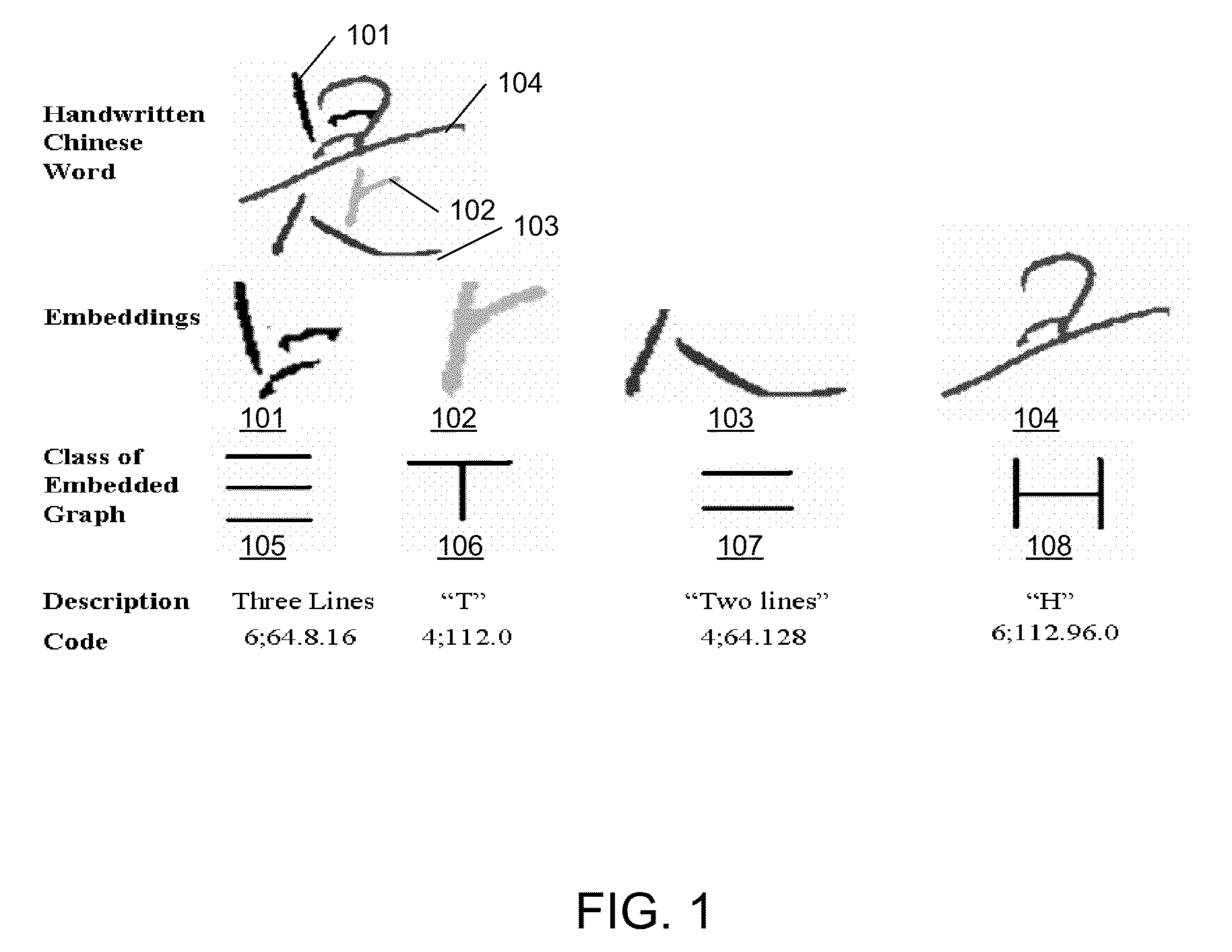
[0022]FIG. 1 is a diagram illustrating example embedded graphs in a Chinese word;

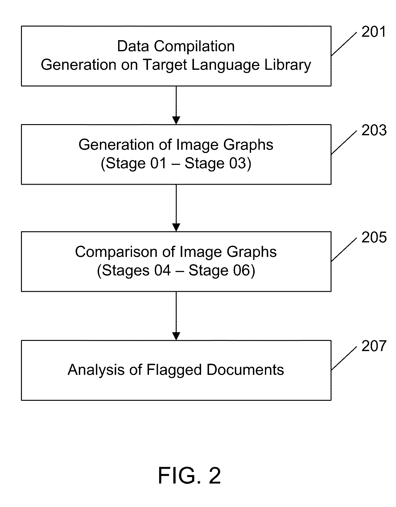
[0023]FIG. 2 is a general diagram outlining a data capture and mining method according to one embodiment;

[0024]FIG. 3 provides a detailed illustration of image graph and image graph library creation according to one embodiment;

[0025]FIG. 4 is a diagram illustrating two example isomorphic graphs;

[0026]FIG. 5 is a diagram illustrating an example process for generating a connectivity key in accordance with one embodiment;

[0027]FIGS. 6A and B are diagrams illustrating embedded graph forms in a finger print;

[0028]FIGS. 7A and B are diagrams illustrating an original fingerprint and ridge lines extracted therefrom;

[0029]FIG. 8 is a diagram illustrating examples of ridge bifurcations and endings in a fingerprint image;

[0030]FIG. 9 is a diagram illustrating examples of var...


PUM


Abstract

A method for fingerprint recognition comprises converting fingerprint specimens into electronic images; converting the electronic images into mathematical graphs that include a vertex and an edge; detecting similarities between a plurality of graphs; aligning vertices and edges of similar graphs; and comparing similar graphs.

Description

RELATED APPLICATIONS INFORMATION[0001]This application claims priority under 35 U.S.C. 119(e) to U.S. Provisional Patent Application Ser. No. 61 / 147,720, entitled “Graph-Based Pattern Recognition Technology Applied to the Automated Identification of Fingerprints,” filed Jan. 27, 2009 and which is incorporated herein by reference in its entirety as if set forth in full.[0002]This application is also related to U.S. patent application Ser. No. 10 / 791,375, entitled “Systems and Methods for Source Language Word Pattern Matching,” filed Mar. 1, 2004 and which is also incorporated herein by reference in its entirety as if set forth in full. This application is also related to U.S. patent application Ser. No. 10 / 936,451, now U.S. Pat. No. 7,362,901, entitled “Systems and Methods for Biometric Identification Using Handwriting Recognition,” filed Sep. 7, 2004 and which is also incorporated herein by reference in its entirety as if set forth in fullBACKGROUND[0003]1. Technical Field[0004]The ...

Claims


Application Information

Patent Timeline
IPC IPC(8): G06K9/68G06T7/00G06K9/46G06V30/10
CPCG06K9/0008G06K2209/01G06K9/469G06K9/001G06V40/1359G06V40/1376G06V30/10G06V30/18181
Inventor WALCH, MARK A.
Owner GANNON TECH GROUP
Learn More