Medical apparatus for collecting fluid

Active Publication Date: 2010-07-29
TALLEY GRP
View PDF22 Cites 40 Cited by
  • Summary
  • Abstract
  • Description
  • Claims
  • Application Information

AI Technical Summary

Benefits of technology

[0011]Advantageously, the fluid inlet is located at or near the top of the fluid collection vessel when the fluid collection vessel is in its preferred orientation. This arrangement prevents the pump having

Problems solved by technology

If a collection vessel is over filled, th

Method used


Image

  • Medical apparatus for collecting fluid
  • Medical apparatus for collecting fluid
  • Medical apparatus for collecting fluid

Examples


Embodiment Construction

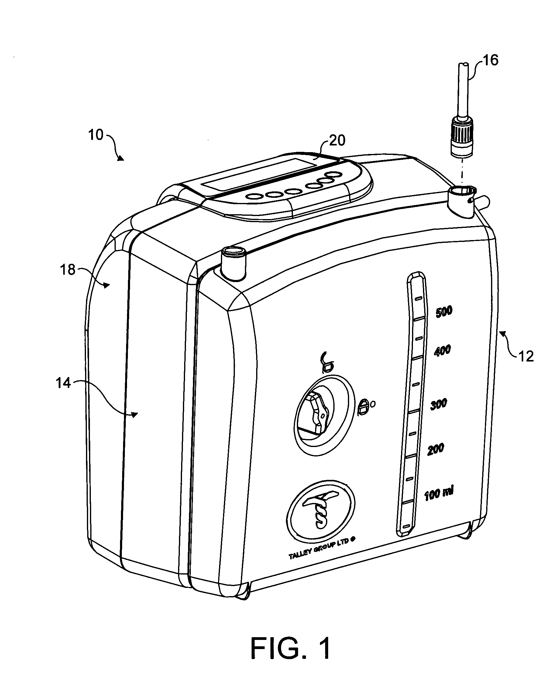
[0036]FIG. 1 shows an embodiment of a medical apparatus 10 for collecting fluid. The medical apparatus 10 is a portable wound treatment apparatus comprising a fluid collection vessel 12, a pump and control assembly 14, a fluid collection conduit in the form of a flexible silicon pipe or tube 16, and a back portion 18. In FIG. 1, the tube 16 is shown disconnected from the fluid collection vessel 12. In use, the tube 16 is connected to the fluid collection vessel 12.

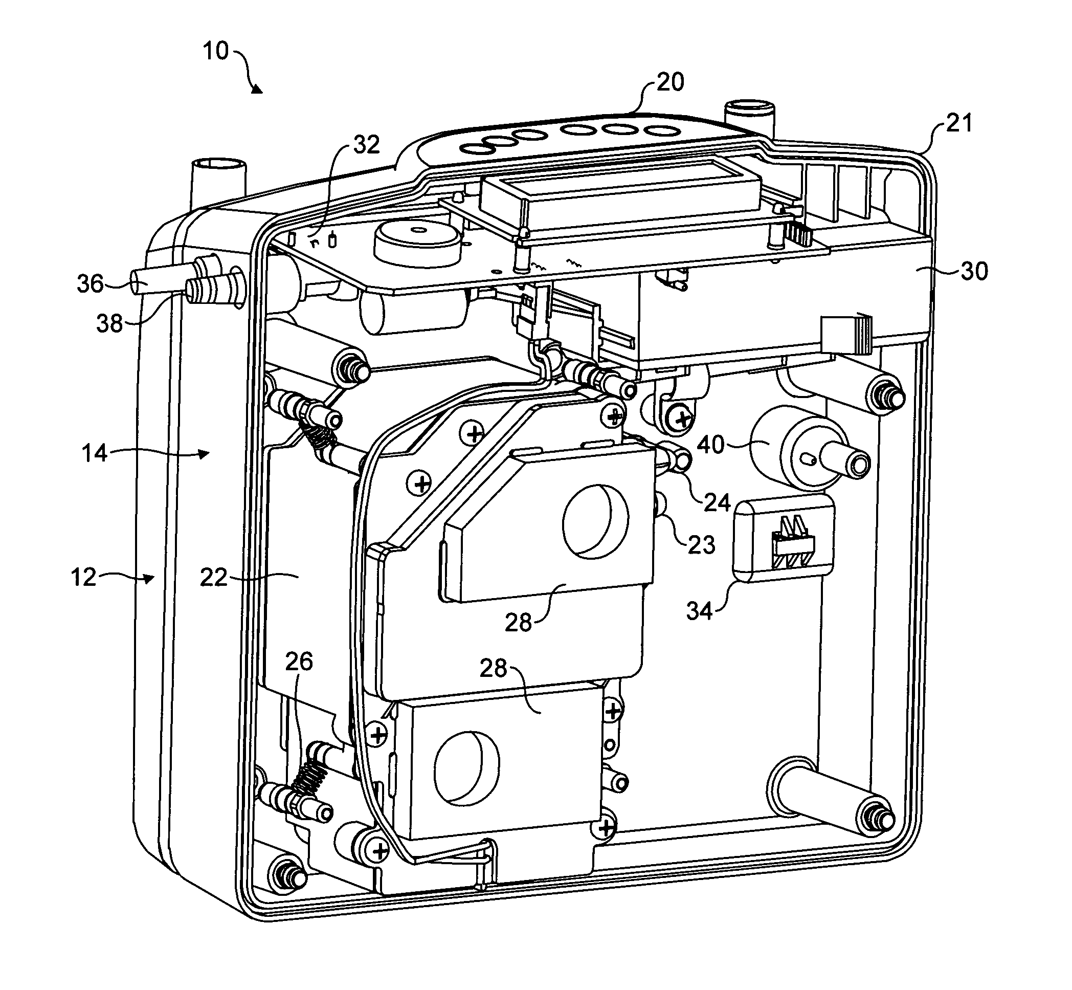
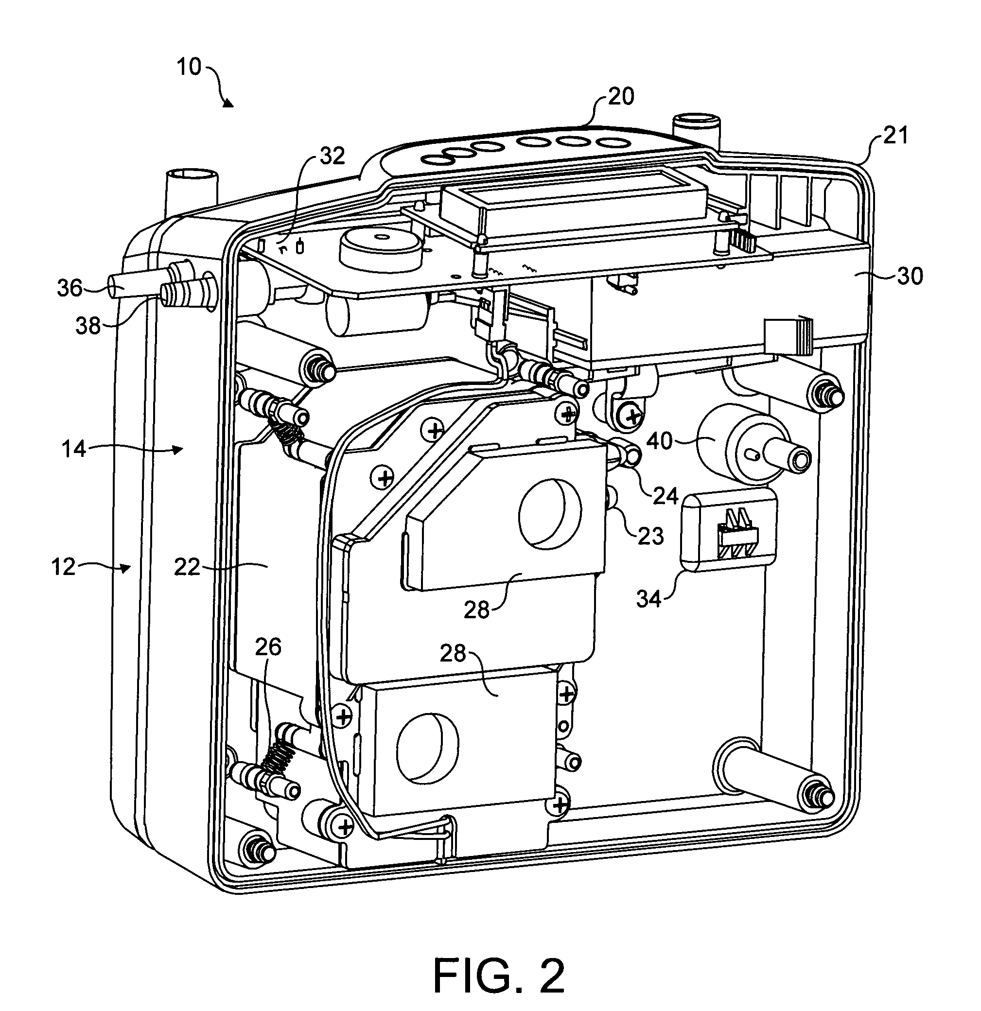
[0037]The pump and control assembly 14 comprises a control panel 20 having a number of function buttons and an LCD display. The pump and control assembly 14 is shown in more detail in FIG. 2 which shows a rear view of the medical apparatus 10 with the back portion 18 removed. As shown in the rear view of FIG. 2, the pump and control assembly 14 of the medical apparatus 10 comprises a housing 21 to house a pump 22 having an air inlet 23 and an air outlet 24, pump suspension springs 26, pump impact snubbers 28, a battery mod...


PUM


Abstract

There is described a medical apparatus, which may comprise a fluid collection vessel and a sensor. The sensor is arranged to sense when the fluid collection vessel is substantially full even when the fluid collection vessel is tilted by up to a predetermined angle from its preferred orientation. The fluid collection vessel may comprise a main chamber and a sensor chamber in fluid communication with one another. The sensor is located in the sensor chamber. The fluid inlet, the main chamber and the sensor chamber are arranged such that fluid entering the fluid collection vessel via the fluid inlet flows into the main chamber even when the fluid collection vessel is tilted by up to the predetermined angle from its preferred orientation, and, once the main chamber is full, any further collected fluid flows from the main chamber into the sensor chamber.

Description

FIELD OF THE INVENTION[0001]The present invention relates to medical apparatus for collecting fluids such as body fluids.BACKGROUND OF THE INVENTION[0002]Medical apparatus exist for collecting fluids or liquids such as body fluids from patients. One example is a wound treatment apparatus for collecting exudate from a wound.[0003]Known wound treatment apparatus generally consist of a tube, often referred to as a drain, extending from the site of fluid collection to a fluid collection vessel. One end of the tube is inserted into a gauze or other permeable material which is placed within the wound at the fluid collection site, and a protective dressing sheet overlies the gauze and the wound. The other end of the tube is connected to the fluid collection vessel. An air pump is used to subject the fluid collection vessel to negative pressure (i.e. a vacuum) so that fluid is removed from the collection site due to the negative pressure gradient between the collection site and the vessel. ...

Claims


Application Information

Patent Timeline
IPC IPC(8): A61M1/00
CPCA61M1/0001A61M2205/3382G01F3/38A61M2205/50A61M2205/3386A61M2205/3379A61M1/0025G01F23/0061A61M1/0031A61M1/0003G01F23/00G01F22/00A61M1/0049A61M2205/3331A61M1/73A61M1/60A61M27/00A61M1/78A61M1/74G01F23/80
Inventor EVANS, JOHN JAMES HENRYCOLE, NICHOLASEVANS, CHRIS
Owner TALLEY GRP
Why Eureka
Try Eureka