Device for locking flexible strands

a flexible strand and mechanical technology, applied in the direction of shoes/pulleys, ropes, shoelace fastenings, etc., can solve the problems of reduced device size, difficult operation, and difficulty in unlocking operation, so as to facilitate the unlocking operation of the locking device, improve the reverse operation, and facilitate the unlocking operation.

Inactive Publication Date: 2010-08-05
SALOMON SA
View PDF21 Cites 13 Cited by
  • Summary
  • Abstract
  • Description
  • Claims
  • Application Information

AI Technical Summary

Benefits of technology

[0017]In view of the foregoing, the invention is directed to an improved locking device that overcomes the aforementioned drawbacks. In particular, the invention facilitates the unlocking operation of a locking device. Similarly, the invention improves upon the reverse operation, i.e., that of locking each strand. In other words, the locking and unlocking operations are made easier and faster.
[0022]The locking device according to the invention is therefore comparable to a clamp that tightens and locks each strand reversibly between the first and second locking zones. The elastic mechanism makes the action of the device constant. The elastic mechanism is used to initiate the locking, which is amplified by the action of each strand on a biasing zone. A mere relative coming closer together of the two biasing zones, obtained for example by a mere grip between the forefinger and the thumb, is sufficient to stop the locking. This handling, carried out against the action of the elastic mechanism, is both simple and fast. The unlocking is thus undertaken in a very simple manner, even for a child, by simply pressing / pinching the biasing zones, the locking occurring automatically as soon as the elastic mechanism is relaxed. Bringing the biasing zones closer together implies a relative spacing apart of the locking zones. As is described below, the invention provides that an increase in the tension of the strands amplifies the locking effect. For example, on an article of footwear, such as a shoe or a boot, the strands which tighten the upper are arranged so as to bias the biasing zones in the direction to space them apart. Thus, an exceptional stress on the upper increases the tightening of the strands.
[0024]Any number of strands, i.e., one or more, can be used. Consequently, the locking device multiplies the arrangement possibilities for managing the tightening of the articles involved. For example, the lacing system of an article of footwear can include one or more strands of a lace, each strand having a specific path.

Problems solved by technology

The unlocking operation is not always easy to carry out, in particular for young children.
To retain the body while moving the pushing member can be a challenge for young children.
This operation is all the more difficult as the size of the device is reduced.
Moreover, the device is often housed in a small and difficult-to-reach area.
As a result, the device is more difficult to reach, which contributes to the difficulty of actuating the pushing member.
Finally, the unlocking operation is even more difficult when the user is wearing gloves, as they hinder the handling of the device.
A difference in tension between two strands does not prevent the locking of one of them.

Method used


Image

  • Device for locking flexible strands
  • Device for locking flexible strands
  • Device for locking flexible strands

Examples


first embodiment

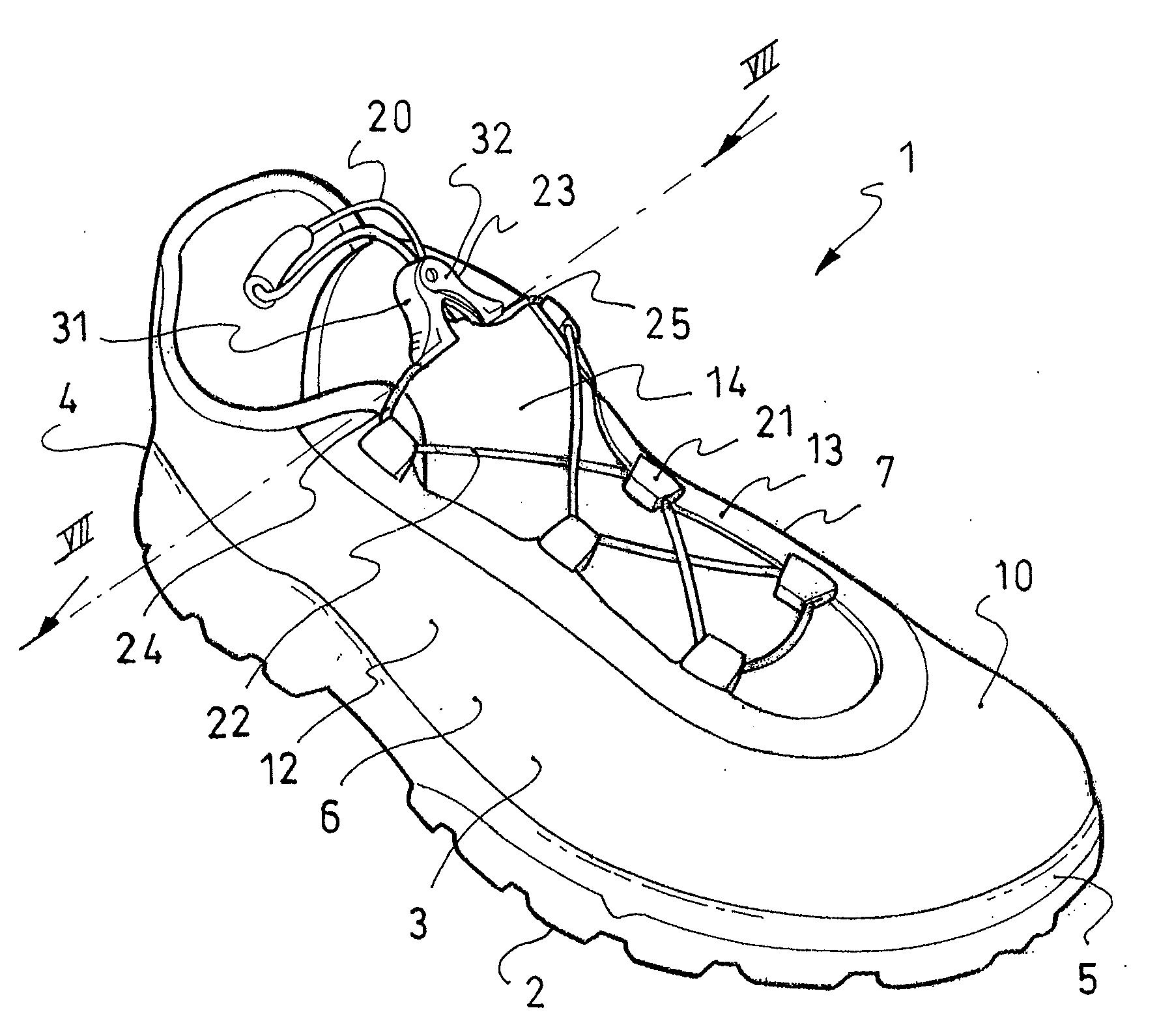
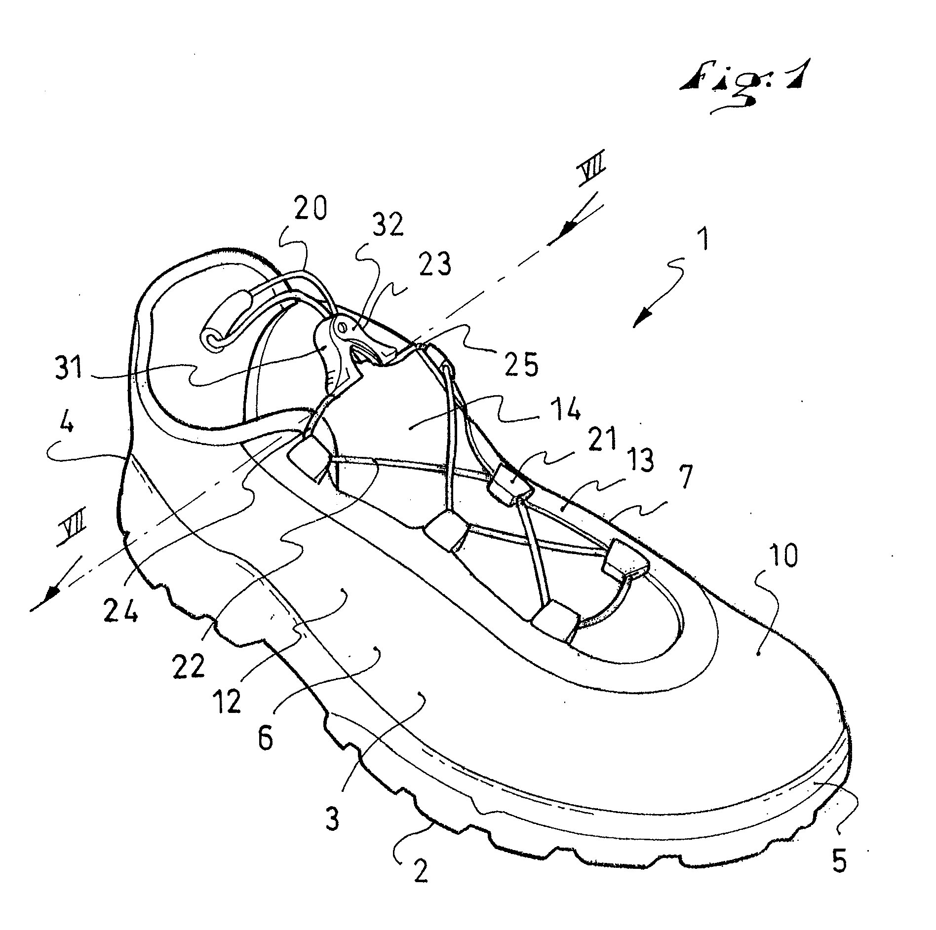
[0039]The first embodiment described hereinafter relates more specifically to shoes for walking or running on flat or uneven ground. However, the invention applies to other fields, such as those mentioned hereinabove, including bags, garments, etc.

[0040]The first embodiment is described hereafter with reference to FIGS. 1 to 9.

[0041]As shown in FIG. 1, a running shoe 1 is adapted to receive the wearer's foot.

[0042]In a known manner, the shoe 1 includes an outer sole assembly 2 and an upper 3 arranged on and secured to the sole assembly. The shoe 1 extends lengthwise between a rear end, or heel 4, and a front end, or tip 5, and widthwise between a lateral side 6 and a medial side 7.

[0043]As shown, the upper 3 includes a lower portion 10, provided to surround the foot, but does not have an upper portion. However, the upper could also be provided to include an upper portion. That is, the illustrated shoe has an upper side that extends below the area of the ankle. However, the upper cou...

second embodiment

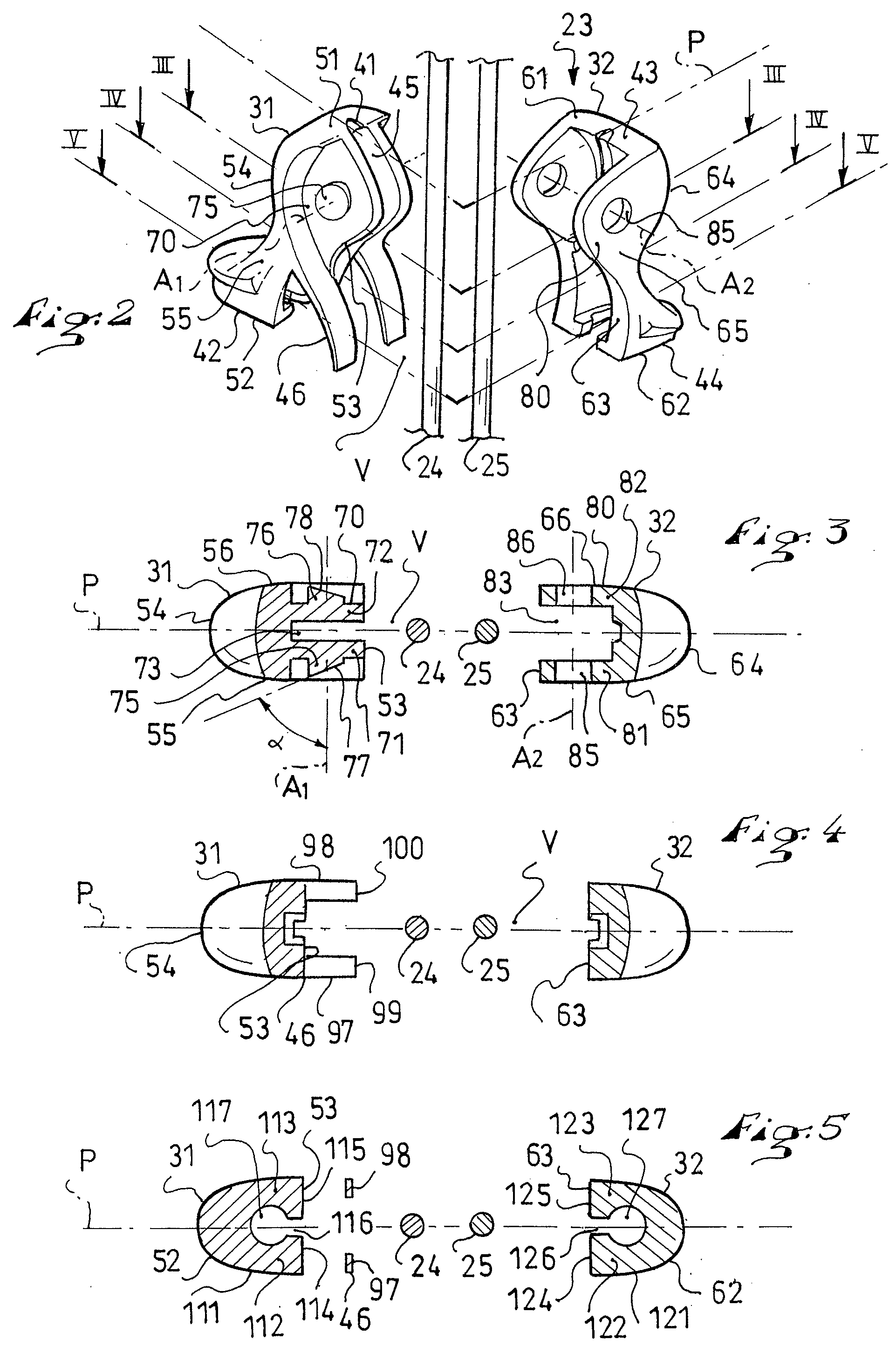
[0081]The second embodiment is shown with reference to FIG. 10. It includes a first portion 31 and a second portion 32 connected to one another by an articulation 40. Again, two strands 24, 25 pass within the locking device 23, in the plane P, between the first ends 51, 61 and the second ends 52, 62.

[0082]What is specific to the second embodiment is the structure of the elastic mechanism designated by the reference numeral 136. This elastic mechanism 136 still includes a first blade 137 and a second blade 138. However, the first blade 137 here projects from the inner side 53 of the first portion 31, in the area of the second end 52, while the second blade 138 projects from the inner side 63 of the second portion 32, in the area of the second end 62. This means that the elastic mechanism 136 is carried by the two portions 31, 32. The operation of the device according to the second embodiment is similar to that according to the first embodiment.

third embodiment

[0083]The third embodiment is shown with reference to FIG. 11. It also includes the portions 31, 32 and the articulation 40, as well as the strands 24, 25.

[0084]What is specific to the third embodiment is again the structure of the elastic mechanism, here identified by reference 146. This elastic mechanism 146 includes a single attached blade 147 that connects the portions 31, 32 to one another, for example from the second end 52 to the second end 62. The blade 147 is generally C-shaped, and includes any suitable material, such as metal, plastic, or the like. The blade 147 is affixed to each portion 31, 32, or to only one, by any appropriate means. According to the third embodiment, the locking device 23 includes three elements.

[0085]The fourth embodiment is shown with reference to FIG. 12. Here, the locking device 23 is identical or similar to that according to the first embodiment. A particular feature of the fourth embodiment relates to the strands 24, 25 of the lace. The first s...


PUM


Abstract

A locking device for at least one strand, including a first portion and a second portion. The device includes an articulation which connects the portions to one another, the first portion having a first locking zone and a first biasing zone, the second portion having a second locking zone and a second biasing zone, the articulation enabling the locking zones to come relatively closer together when the biasing zones move away from one another, and vice versa, the locking device further including a primary guide which retains each strand between the locking zones, as well as an elastic mechanism which biases the locking zones toward one another.

Description

CROSS-REFERENCE TO RELATED APPLICATION[0001]This application claims priority under 35 U.S.C. §119 of French Patent Application No. 09.00377, filed on Jan. 29, 2009, the disclosure of which is hereby incorporated by reference thereto in its entirety.BACKGROUND[0002]1. Field of the Invention[0003]The invention relates to a mechanical device for locking flexible strands, such as cords, threads, laces, other filiform elements, and any other product having the same or similar attribute(s).[0004]The invention relates, according to particular embodiments, to the locking or blocking of laces for articles of footwear, or laces for other clothing or storage articles.[0005]In more particular embodiments, the invention relates to the field of sports, and in particular to walking shoes, running shoes, hiking shoes, cycling shoes, cross-country ski shoes or boots, snowboard boots, alpine and other ski boots, and the like. The invention relates to any article that requires closing or tightening, s...

Claims


Application Information

Patent Timeline
Patent Type & Authority Applications(United States)
IPC IPC(8): A43C11/00A43C7/00
CPCA43C7/00Y10T24/3732F16G11/10F16G11/101
Inventor LEICK, PATRICK
Owner SALOMON SA
Why Eureka
Try Eureka