Rain water diverter

a technology of rainwater and sluice valve, which is applied in the direction of roof drainage, mechanical equipment, transportation and packaging, etc., can solve the problems of water being used for consumption, water being scarce for a long time, and water being used for watering. and other problems, to achieve the effect of reducing the amount of debris in the rainwater exiting the first outlet with surface tension and surface area

Inactive Publication Date: 2010-08-05
SUSTAIN LLC +1
View PDF23 Cites 35 Cited by
  • Summary
  • Abstract
  • Description
  • Claims
  • Application Information

AI Technical Summary

Problems solved by technology

In some parts of the country water has always been scarce, needing to be obtained from hundreds, if not thousands of miles away.
However, with mounting pressure from droughts, irrigation, and population growth, there have been reports of ground water levels dropping and rivers drying up.
In addition, when outfitted with filters or other water purification devices, the water can also be used for consumption.
However, once the barrel is full, water flows out from the barrel, which can cause problems with flooding the area surrounding the barrel and even the building to which the downspout is attached.
This problem can also occur where a rain water collection system includes a diverter, which is a device that attaches to a downspout and diverts water to a barrel or other water collection container.
Additional problems associated with previous rain water collection systems include the collected water containing debris such as leaves and berries.
There can also be issues with the rain barrel not being properly secured to a building to which a downspout feeding the rain barrel in attached.
Winter maintenance, especially in climates with freezing temperatures, can be a problem for rain water collection systems.
Some rain water collection systems are difficult to assemble.
Rain water collection systems can also suffer from low flow rates of collected water flowing out of the rain barrel or other collection device.
Where the rain water collection systems are not closed systems, bugs, such as mosquitoes are attracted to the water, lay their eggs in the water, and once hatched, carry disease and irritation to nearby humans.
Rain water collection systems employing clear plastic can also suffer from algae growth.

Method used


Image

  • Rain water diverter
  • Rain water diverter
  • Rain water diverter

Examples


Embodiment Construction

Construction and Operation of Embodiments of the Invention

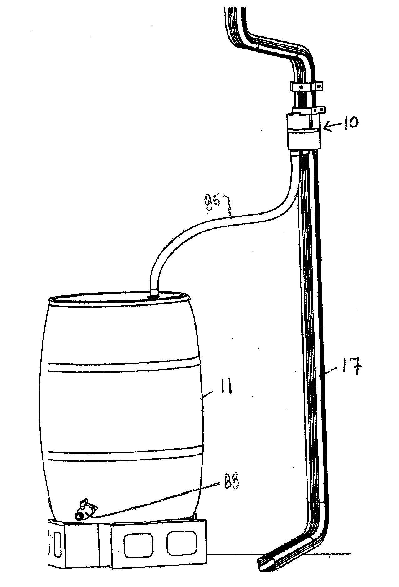
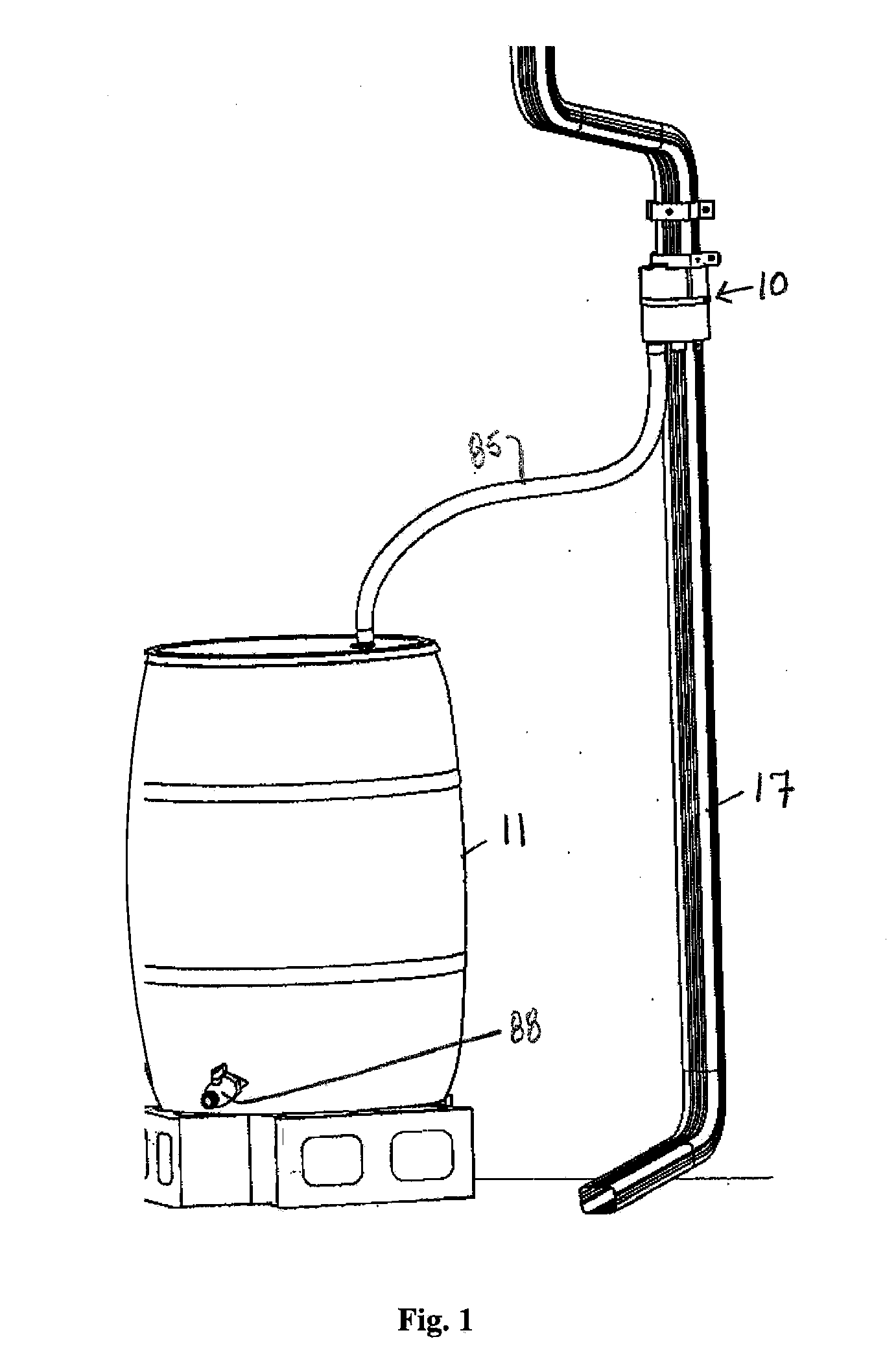
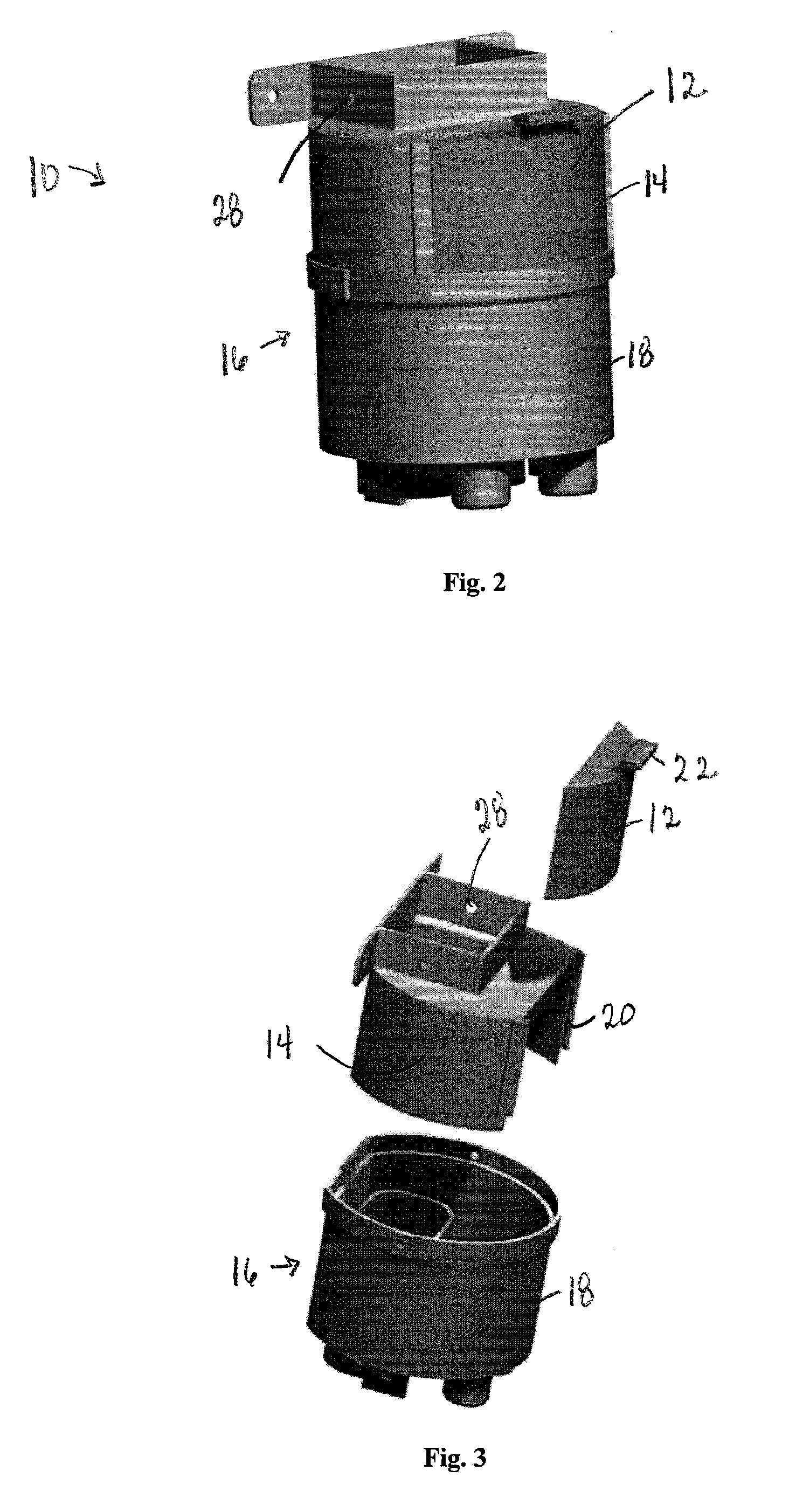
[0026]Referring initially to FIG. 1, in at least one embodiment, a diverter 10 is fluidically coupled to a container 11 for holding collected rain water that is diverted to it from a downspout 17. Referring now to FIGS. 2-7, an embodiment of a diverter 10 includes a housing 16 and a door 12, an upper portion 14 of the housing 16, and a lower portion 18 of the housing 16. In one embodiment, the door 12 and the housing 16 are made from a corn-based plastic such as polylactic acid (PLA). In an embodiment, the door 12 and the housing 16 are made from a mixture of 49% PLA, 49% acrylic, and 2% color additives by weight. Mixing materials raises the heat deflection temperature of the PLA, to withstand high temperatures. The acrylic improves the surface finish, UV resistance, and strength of the final product. Additional materials can be used instead of, or in addition to the acrylic, such as polycarbonate,) and 2% color additives. Th...


PUM


Abstract

A device for separating water from debris and collecting rain water includes an upper portion and a lower portion. The upper portion includes an inlet and a structure for separating water from debris with surface tension and surface area. The lower portion is removably mounted to the upper portion and includes a first outlet configured to be fluidically coupled to a downspout and a second outlet configured to be fluidically coupled to a container for holding collected rain water. A rain water collection system including the device is also provided, as well as a method of using the device.

Description

CROSS-REFERENCE TO RELATED APPLICATIONS[0001]This application claims priority under 35 U.S.C. §119(e) to U.S. Provisional Patent Application No. 60 / 955,126, filed Aug. 10, 2007, the entirety of which is incorporated by reference herein.FIELD OF THE INVENTION[0002]The invention relates to water conservation and reclamation and more particularly to a system and method for reclaiming and recovering rain water.DESCRIPTION OF THE RELATED ART[0003]Water is a precious resource that must be conserved. In some parts of the country water has always been scarce, needing to be obtained from hundreds, if not thousands of miles away. In other parts of the country, water has been plentiful. However, with mounting pressure from droughts, irrigation, and population growth, there have been reports of ground water levels dropping and rivers drying up.[0004]One solution to address water shortage is to collect rain water from roof into rain barrels or cisterns. Collected water can be used for watering y...

Claims


Application Information

Patent Timeline
Patent Type & Authority Applications(United States)
IPC IPC(8): F16L5/00E04D13/08
CPCE04D13/08E04D2013/0813F16L55/24E04D2013/0866E04D2013/086Y10T137/6969
Inventor MORODER, BRYANT MATTHEWGALAL, OMAR MOSTAFAGUITHER, JAMES E.
Owner SUSTAIN LLC
Why Eureka
Try Eureka