Gutter emptying system

Inactive Publication Date: 2006-12-26
WYATT CHRIS ROGER
View PDF6 Cites 13 Cited by
  • Summary
  • Abstract
  • Description
  • Claims
  • Application Information

AI Technical Summary

Problems solved by technology

These systems may function well, however, they are eyesores with chains, pulleys, and levers either exposed or in some cumbersome housing.

Method used


Image

  • Gutter emptying system
  • Gutter emptying system
  • Gutter emptying system

Examples


Embodiment Construction

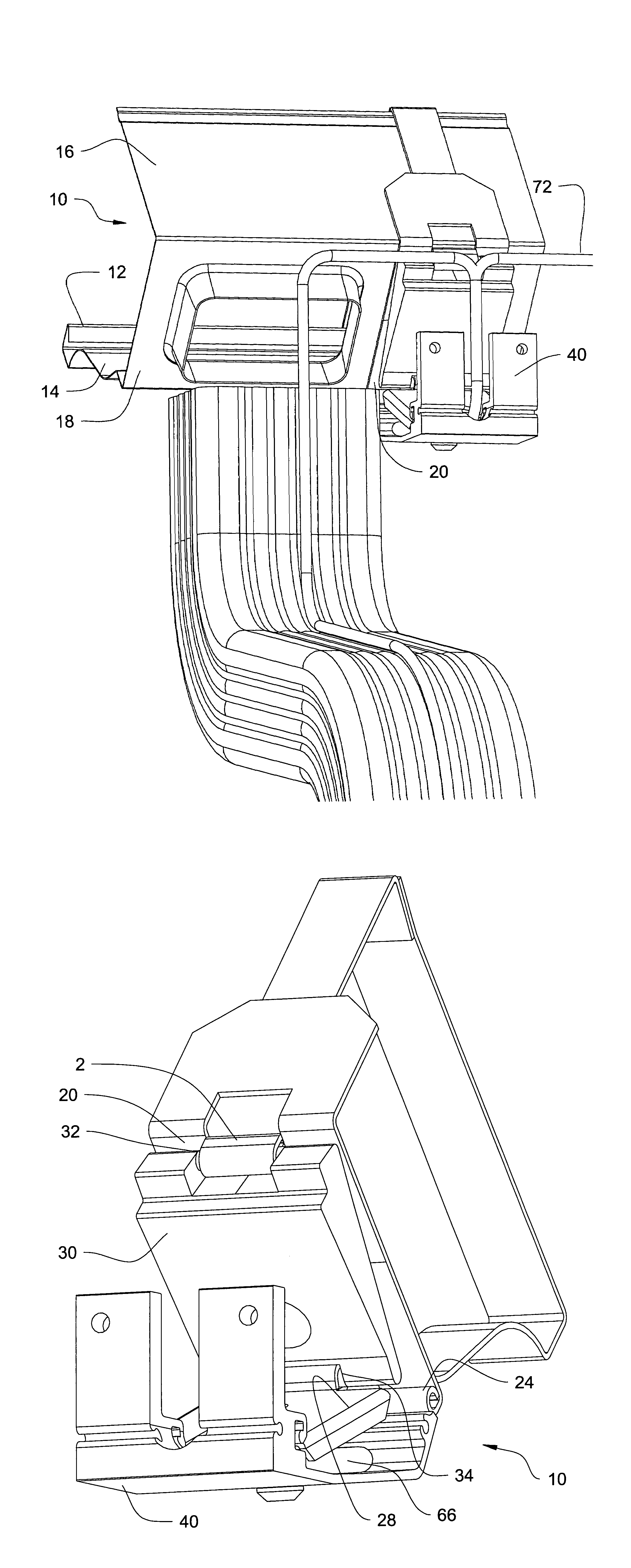
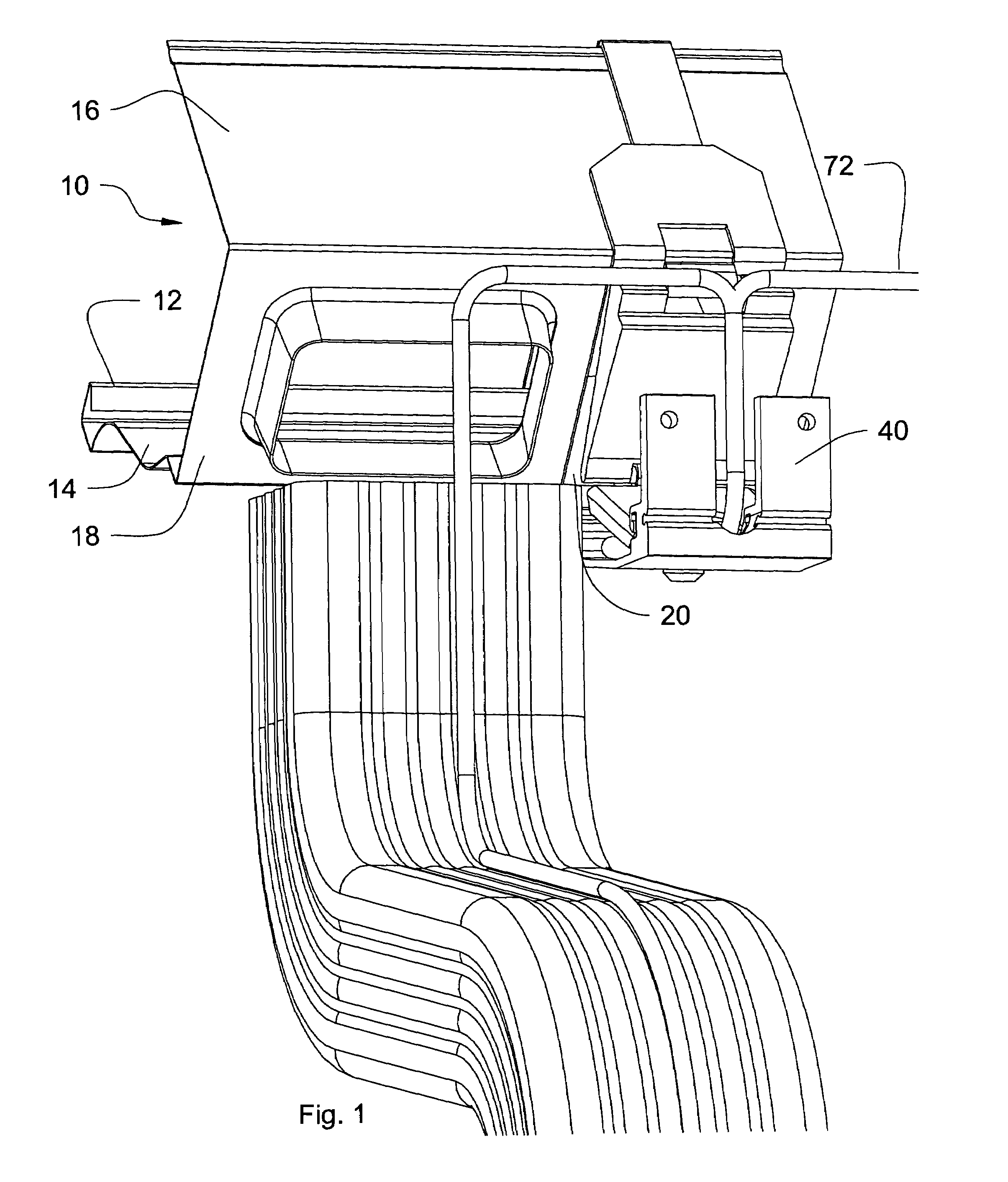
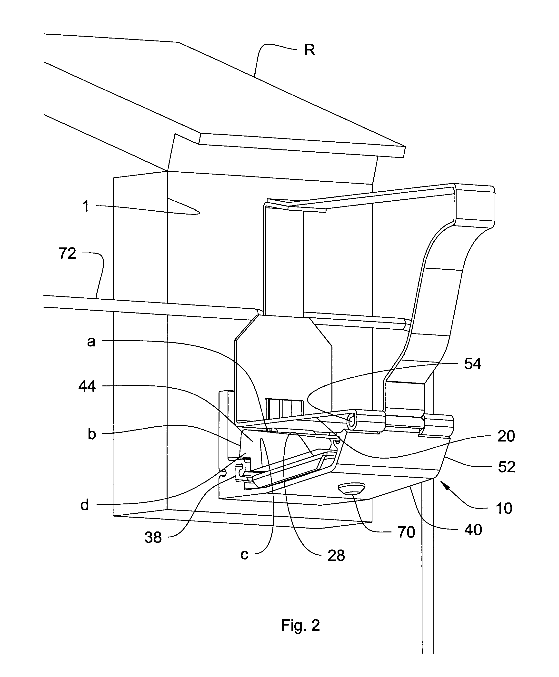
[0005]Referring to the drawings, FIGS. 1–12, a gutter emptying system is shown. FIG. 1 shows a perspective view of the rear of the system in it's partially tilted position for emptying with downspout drain detail, FIG. 2 shows the bracket for holding the gutter in the receiving position, FIG. 3 shows the system in it's partially tilted position, FIG. 4 shows the bracket per se, FIG. 5 is a second embodiment of the bracket housing, FIG. 6 is another second embodiment of the bracket housing, FIG. 7 shows alternate form of the gutter shape to accommodate a gutter engaging bracket with a clampon to assist in holding the bracket to the gutter, FIG. 8 shows an alternate form of the gutter shape to accommodate a twist in the bracket as a second embodiment, FIG. 9 shows a second embodiment for holding an arcuate shaped gutter, FIG. 10 shows an air or liquid pressure system for activating the device, FIG. 11 shows a second embodiment of the bracket housing and a second embodiment of bracket ...


PUM


Abstract

This invention permits use of a conventional rain gutter system and downspout, and other gutter profiles as described to be converted into a dumpable rain gutter system which can be easily cleaned. This low profile gutter tilting system, which has few moving parts, low noise level, and no unsightly housing or exposed parts, comprises a plurality of gutter supports. This system uses air or liquid as a means to activate a rotating mechanism concealed inside the supports to pivot the gutter about a common point, as to empty any debris not normally washed out of a downspout or gutter system. The system includes, in general an OG type gutter, and a gutter support, which mounts to a building facia or trim board. The gutter supports include a hinge where a first free end is connected to the back bottom edge of a gutter, and a second free end of the hinge is connected to a stationary housing that mounts to the facia board and supports a gutter. The front bottom edge is pivotally connected to the stationary housing. An inflatable device in the stationary housing is placed between the hinge and the stationary housing to pivot the hinge, thereby lifting the rear of the gutter due to the front edge being pivotally connected to the stationary housing until the hinge is fully open, emptying the gutter of debris. A weight is affixed to the first free end of the hinge whereby the gutter, after emptying, will be partially retracted to it's water and debris collecting position by the resiliency of the inflatable device or bladder, and fully retracted by the pull of the weight, and or the vacuum created by the drainage of liquid from the system when a liquid is used as the inflatable means.

Description

BACKGROUND OF THE INVENTION[0001]The present invention relates to a gutter system for collecting rain and, incidentally, debris from trees and emptying any debris not normally washed out of a downspout, and in particular, to a gutter and gutter emptying system.[0002]It is well known that gutters collect water, rain or snow, and dispense it through a downspout. It is also known to pivot or rotate the gutter to empty any debris from trees, such as leaves and twigs. The patented art clearly exhibited several systems for emptying debris. One popular system includes a support mounted to a fascia board and pivotally connected to the bottom front edge of a gutter to pivot about the front edge, U.S. Pat. No. 5,649,681 to Fave, for example. Another popular system also provides a pivotal support, however the gutter pivots about the bottom back edge (see U.S. Pat. No. 5,417,015 Coyne). There is also a body of art where a gutter is rotatably mounted on a shaft, for example, U.S. Pat. No. 4,061,...

Claims


Application Information

Patent Timeline
Patent Type & Authority Patents(United States)
IPC IPC(8): E04D13/072
CPCE04D13/064
Inventor WYATT, CHRIS ROGER
Owner WYATT CHRIS ROGER
Why Eureka
Try Eureka