Apparatus for the collection of rainwater from a downpipe

Inactive Publication Date: 2013-09-26
BLAIR CHRISTOPHER DOUGLAS
View PDF13 Cites 13 Cited by
  • Summary
  • Abstract
  • Description
  • Claims
  • Application Information

AI Technical Summary

Benefits of technology

[0011]The invention is an apparatus that facilitates the collection of rainwater flowing through a substantially vertical pipe such as a downspout from the eaves of a house. The bottom of the pipe is substantially seale

Problems solved by technology

In many parts of the world, water is scarce and becoming scarcer.
However, adding rainwater collection to an exi

Method used


Image

  • Apparatus for the collection of rainwater from a downpipe
  • Apparatus for the collection of rainwater from a downpipe
  • Apparatus for the collection of rainwater from a downpipe

Examples


Embodiment Construction

[0024]The inventor has conceived, and reduced to practice, an apparatus for the collection of rainwater from a downpipe that addresses the challenges and problems in the art outlined above. Various techniques will now be described in detail with reference to a few example embodiments thereof, as illustrated in the accompanying drawings. In the following description, numerous specific details are set forth in order to provide a thorough understanding of one or more aspects and / or features described or referenced herein. However, it will be apparent to one skilled in the art, that one or more aspects and / or features described or referenced herein may be practiced without some or all of these specific details. In other instances, well known process steps and / or structures have not been described in detail in order to not obscure some of the aspects and / or features described or reference herein.

[0025]One or more different inventions may be described in the present application. Further, ...


PUM


Abstract

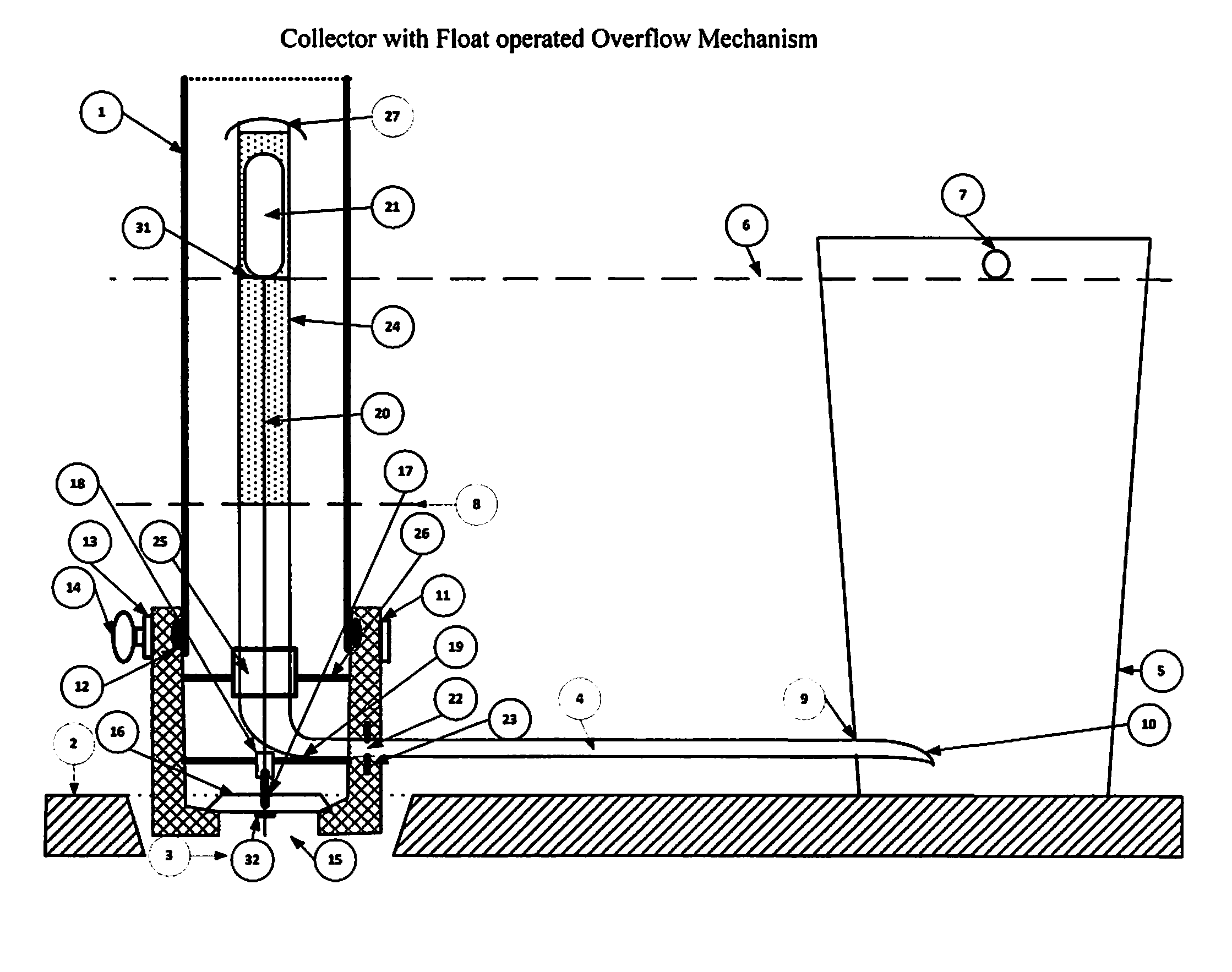
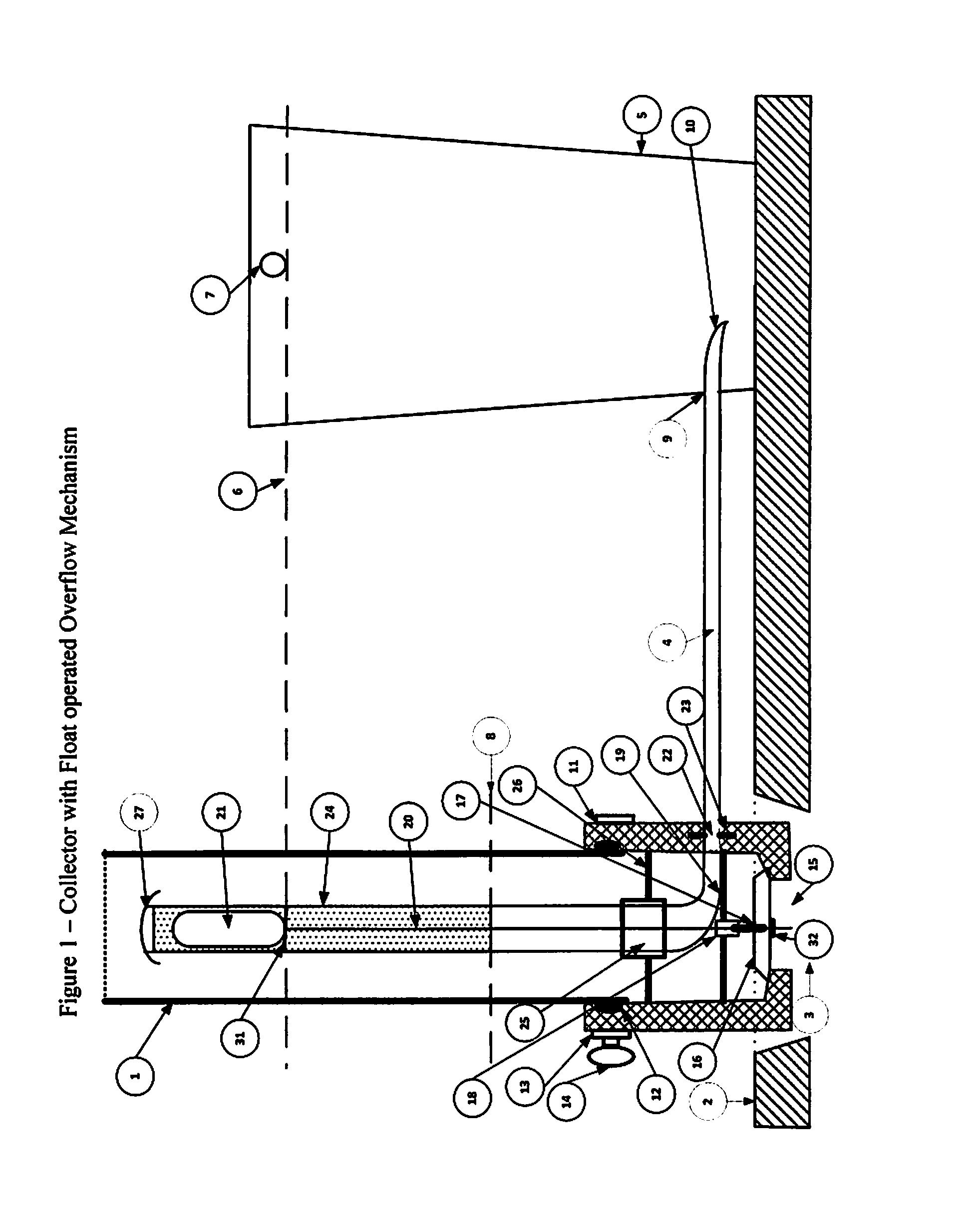
A pipe of diameter significantly less than that of the downpipe is inserted up from the bottom of the downpipe and extends up the inside of the downpipe. The upper face of this inner tube is sealed so that water does not pour into its end. The wall of the inner tube is perforated so that water can flow into it from the sides as and when the downpipe fills with water to that level. The other end of this tube is in communication with the water butt allowing the water to flow from the downpipe to the water butt until the levels equalize or that in the downpipe falls below the level of said perforations.

Description

RELATED APPLICATIONS[0001]This application is the national stage entry of, and claims priority to, UK patent application serial number GB 1204979.7, titled “Apparatus for the collection of rainwater from a downpipe”, and filed on Mar. 21, 2012, the entire specification of which is hereby incorporated by reference.BACKGROUND OF THE INVENTION[0002]1. Field of the Invention[0003]This invention pertains to water collection generally, and more particularly to collection of rainwater from building runoff.[0004]2. Discussion of the State of the Art[0005]Getting the rainwater from the roof on which it falls into a suitable holding tank can be achieved simply by placing a tank (also known as a “water butt” or, in the United States, a “rain barrel”) under the open end of a downpipe (or “downspout”) connected directly or indirectly to the guttering around the roof. Water simply flows down the pipe and into the barrel.[0006]However, there are a number of disadvantages to this approach. The loca...

Claims


Application Information

Patent Timeline
IPC IPC(8): E03B1/04
CPCE03B3/02E03B1/04E04D2013/082E04D2013/0806E04D13/08Y02A20/108Y10T137/6969
Inventor BLAIR, CHRISTOPHER DOUGLAS
Owner BLAIR CHRISTOPHER DOUGLAS
Why Eureka
Try Eureka