Microparticle measuring apparatus and microparticle measuring method

a technology of microparticles and measuring devices, applied in the field of microparticles, can solve the problems of reducing accuracy, testing cannot be quickly performed, and testing cannot be simply performed, and achieve the effect of reducing the solution electric conductivity

Inactive Publication Date: 2010-08-05
PANASONIC HEALTHCARE HLDG CO LTD
View PDF10 Cites 15 Cited by
  • Summary
  • Abstract
  • Description
  • Claims
  • Application Information

AI Technical Summary

Problems solved by technology

However, the colonization requires usually one to two days, or several weeks depending on the kind of microorganisms, and hence there is a problem in that the test cannot be rapidly performed.
Consequently, there are problems in that the test cannot be simply performed, and that the accuracy is lowered by operational variations.
In the case where it is assumed that a sample liquid such as described above is measured by the conventional DEPIM method, therefore, there is a problem in that, in a sample which has a high sample liquid electric conductivity, the dielectrophoretic force acting on microorganisms is reduced, and the number of microorganisms collected on microelectrodes is decreased, with the result that the measurement sensitivity is lowered.
Moreover, the dielectrophoretic force acting on microorganisms is different depending on the sample liquid electric conductivity, and hence there is a problem in that, when sample liquids of different electric conductivities are measured, the dispersion of measurement results is large.

Method used


Image

  • Microparticle measuring apparatus and microparticle measuring method
  • Microparticle measuring apparatus and microparticle measuring method
  • Microparticle measuring apparatus and microparticle measuring method

Examples


first embodiment

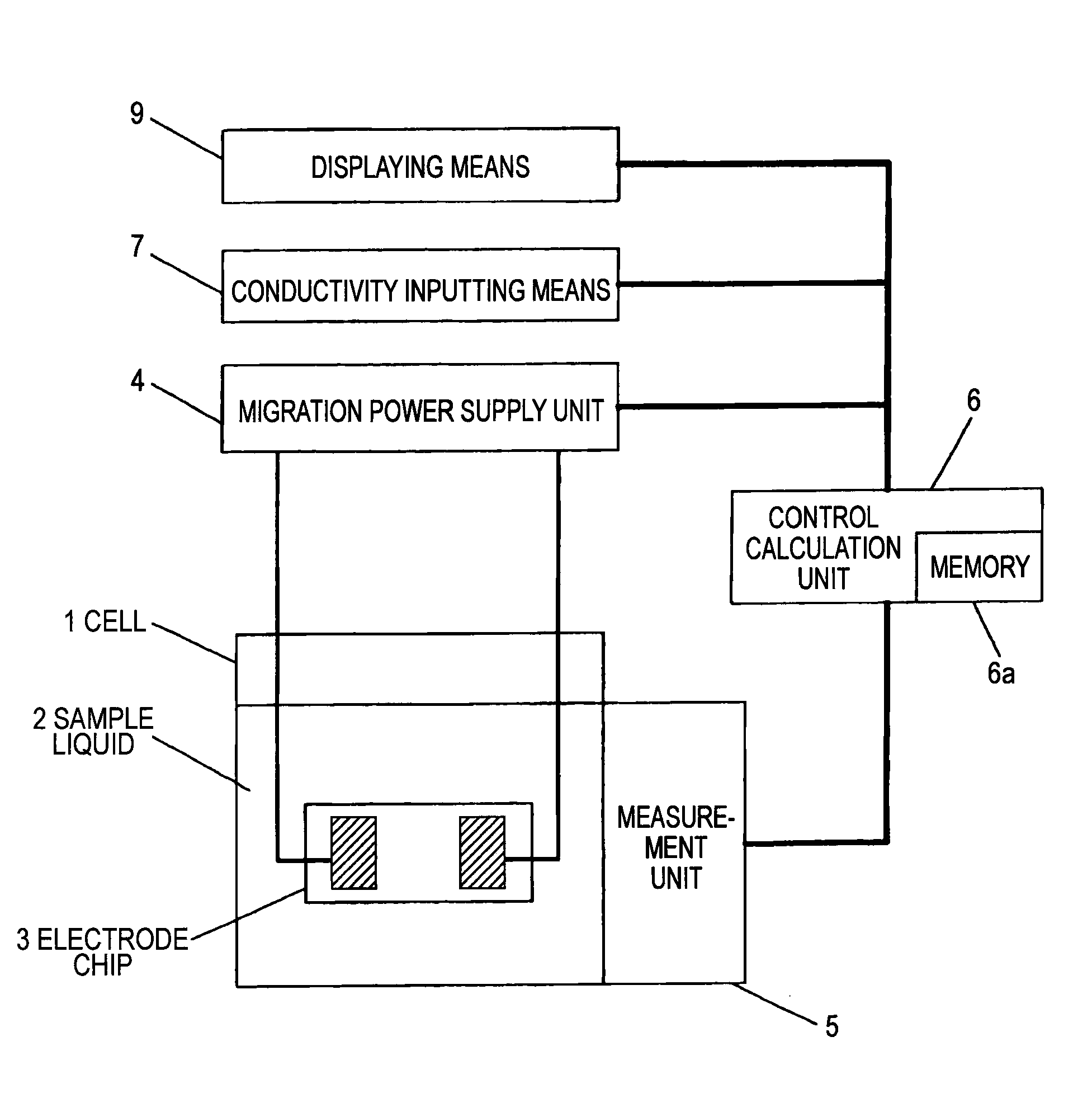
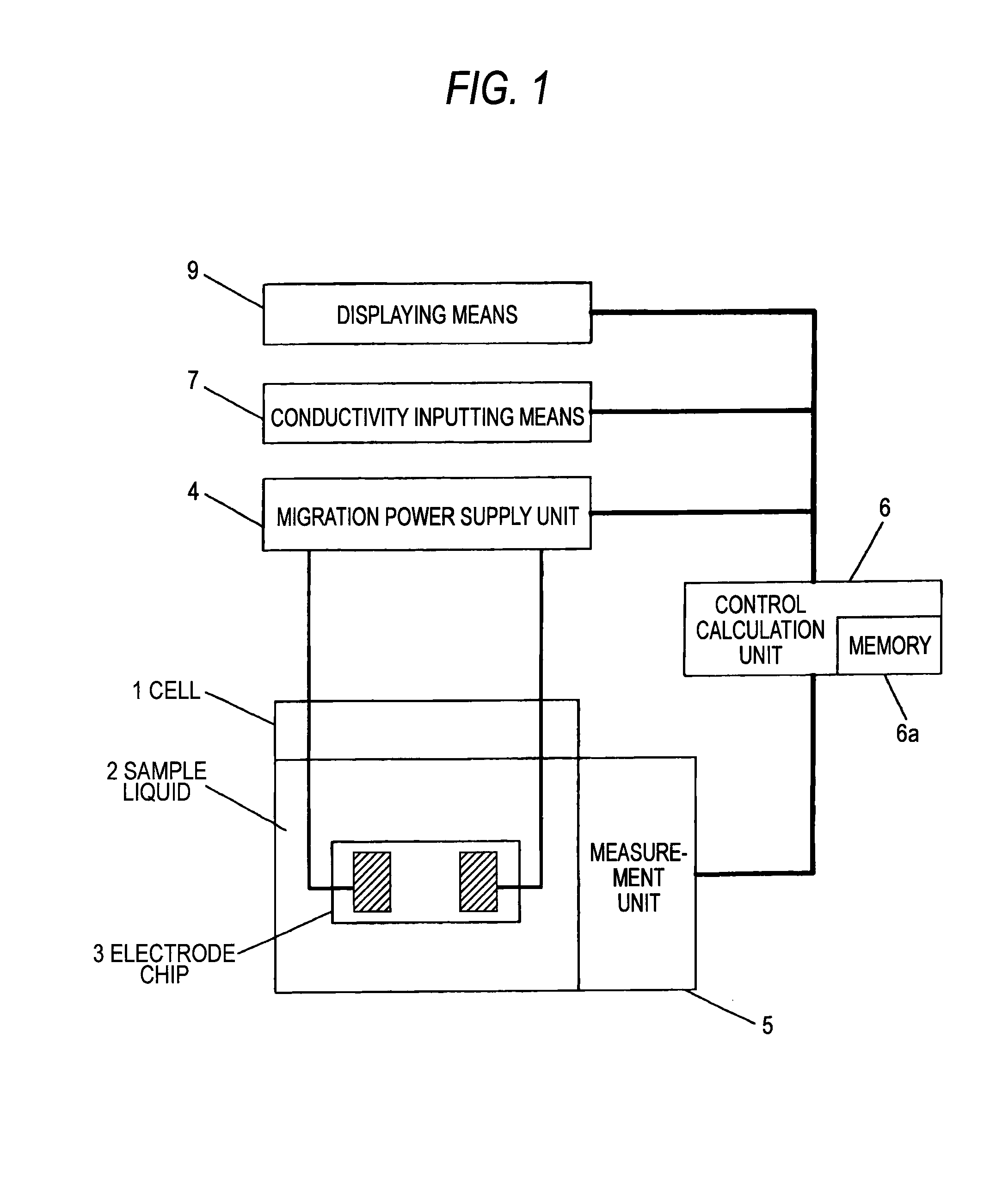
[0138]Hereinafter, a microorganism measuring apparatus of an embodiment of the invention will be described with reference to the drawings. FIG. 1 is a configuration diagram of the microorganism measuring apparatus of the embodiment, and FIG. 2 is a schematic view illustrating an electrode chip of the microorganism measuring apparatus of the embodiment.

[0139]Referring to FIG. 1, 1 denotes a cell which holds a sample liquid 2 containing microorganisms to be measured, 3 denotes an electrode chip including an electrode pair which collects the microorganisms by dielectrophoresis, 4 denotes a migration power supply unit, 5 denotes a measurement unit which measures a optical or electrical change caused by microorganisms that are trapped by dielectrophoresis, 6 denotes a control calculation unit which performs a control on the whole microorganism measuring apparatus, analysis calculation of measurement results, input / output processes, and the like, and 7 denotes conductivity inputting means...

second embodiment

[0185]Hereinafter, a microorganism measuring apparatus of an embodiment of the invention will be described with reference to the drawings. FIG. 10 is a configuration diagram of the microorganism measuring apparatus of the embodiment.

[0186]Referring to FIG. 10, 1 denotes a cell which holds a sample liquid 2 containing microorganisms to be measured, 3 denotes an electrode chip including an electrode pair which collects the microorganisms by dielectrophoresis, 4 denotes a migration power supply unit, 5 denotes a measurement unit which measures the inter-electrode impedance, and 6 denotes a control calculation unit which performs a control on the whole microorganism measuring apparatus, calculations such as an impedance calculation, and the like.

[0187]As shown in FIG. 2, 10 denotes a substrate, and 11a and 11b denote electrodes which are formed on the substrate 10, and which constitute a pair of poles. On the substrate 10, patterns of the electrode 11a, 11b are formed by an electrically...

third embodiment

Electric Conductivity Measurement Unit

[0246]The description of the portions which are duplicated with the above-described embodiments is omitted. FIG. 17 is a configuration diagram of a microparticle measuring apparatus showing the embodiment. Conductivity measuring means 101 is placed at a position where the means is impregnated in the sample liquid 2 of the cell 1. As the conductivity measuring means 101, a usual electric conductivity measuring apparatus may be used. For example, the means is configured by electrodes for measuring the AC conductivity, and voltage applying means. The conductivity measuring means 101 is connected to the control calculation unit 6, and a result of the conductivity measurement is sent to the control calculation unit 6.

[0247]Alternatively, the electrode chip 3 may function also as the electrodes for measuring the electric conductivity. The migration power supply unit 4 which can apply an AC voltage, and the measurement unit 5 for measuring an impedance...


PUM

PropertyMeasurementUnit
frequencyaaaaaaaaaa
electric conductivityaaaaaaaaaa
frequencyaaaaaaaaaa

Abstract

A microparticle measuring apparatus and microparticle measuring method which, in sample liquids having different electric conductivities, have a sensitivity and accuracy which are necessary and sufficient, without performing pretreatment of reducing the electric conductivity are provided. The microparticle measuring apparatus includes: a cell 1 into which a liquid containing microparticles is to be introduced; at least one pair of electrodes which are immersed in the cell 1; a migration power supply unit 4 which applies an AC voltage of a frequency at which a dielectrophoretic force on the microparticles is equal to or larger than a predetermined value, between the pair of electrodes; a measurement unit 5 which measures the microparticles in the cell; and a control calculation unit 6 which calculates a result of the measurement performed by the measurement unit, and which calculates the concentration of the microparticles in the liquid.

Description

TECHNICAL FIELD[0001]The present invention relates to a microparticle measuring apparatus and microparticle measuring method for measuring the number of microparticles in a sample liquid by using dielectrophoresis, and more particularly to a microparticle measuring apparatus and microparticle measuring method in which an influence of the electric conductivity of a solution is avoided without performing pretreatment, and which performs measurement highly sensitively and highly accurately.BACKGROUND ART[0002]Recently, it is particularly highly needed to rapidly, simply, and highly sensitively perform a quantitative measurement on microorganisms which may cause food poisoning or an infectious disease to do any harm to the human body, because, in a step of producing food, a clinic unequipped with a microorganisms test facility, or the like, when a microorganisms test is performed on the spot, it is possible to prevent food poisoning or an infectious disease from occurring.[0003]In a so-...

Claims


Application Information

Patent Timeline
Patent Type & Authority Applications(United States)
IPC IPC(8): G01N27/447
CPCC12Q1/18G01N27/447G01N15/0656
Inventor HAMADA, RYOU
Owner PANASONIC HEALTHCARE HLDG CO LTD
Why Eureka
Try Eureka