Apparatus for Pathogen Detection

a technology for pathogen detection and apparatus, applied in the field of apparatus for pathogen detection, can solve the problems of high cost, inability to detect pathogens, and inability to detect pathogens, and achieve the effect of maximizing separation, differentiation, capture or release of analy

Active Publication Date: 2015-04-23
FLUID SCREEN INC
View PDF4 Cites 16 Cited by
  • Summary
  • Abstract
  • Description
  • Claims
  • Application Information

AI Technical Summary

Benefits of technology

[0044]The step of detecting low amounts of analyte using a microfluidic sensor includes using an electric field at predetermined flow conditions, to immobilize the analyte on the surface of a field effect based sensor, nanowire sensor, nanoribbon sensor, or ion sensitive field effect transistor sensor.
[0045]Super positioning or tuning of frequency components, waveform shapes, and waveform tunings, or any combination thereof, may be performed to maximize separation, differentiation, capture, or release of the analyte.

Problems solved by technology

Conventional detection methods have proven inadequate because they suffer from long incubation periods, high cost, and require highly trained personnel to operate.
Conventional methods rely on bacterial culture growth, which require highly qualified personnel and time, both contributing to higher costs for the procedure.
Although faster methods, such as PCR (Polymerase Chain Reaction) Plates or labeled detection and fluorescent imaging, can reduce the response time to one hour, these require complex sample preparation, highly trained personnel, high cost per test, and have limited portability.
The major challenge in automated sample preparation for detection from blood or other unprocessed liquids using microstructures is efficient separation of the analyte of interest (bacteria, cells, or particles) from large blood components.
RBC and WBC presence obstructs the detection of bacteria, cells, or particles.
However, effective methods for cell / pathogen separation on a micro-scale from fluids containing pollutants of comparable size are still unattainable.

Method used


Image

  • Apparatus for Pathogen Detection
  • Apparatus for Pathogen Detection
  • Apparatus for Pathogen Detection

Examples


Embodiment Construction

)

[0073]In describing the preferred embodiment of the present invention, reference will be made herein to FIGS. 1-24 of the drawings in which like numerals refer to like features of the invention.

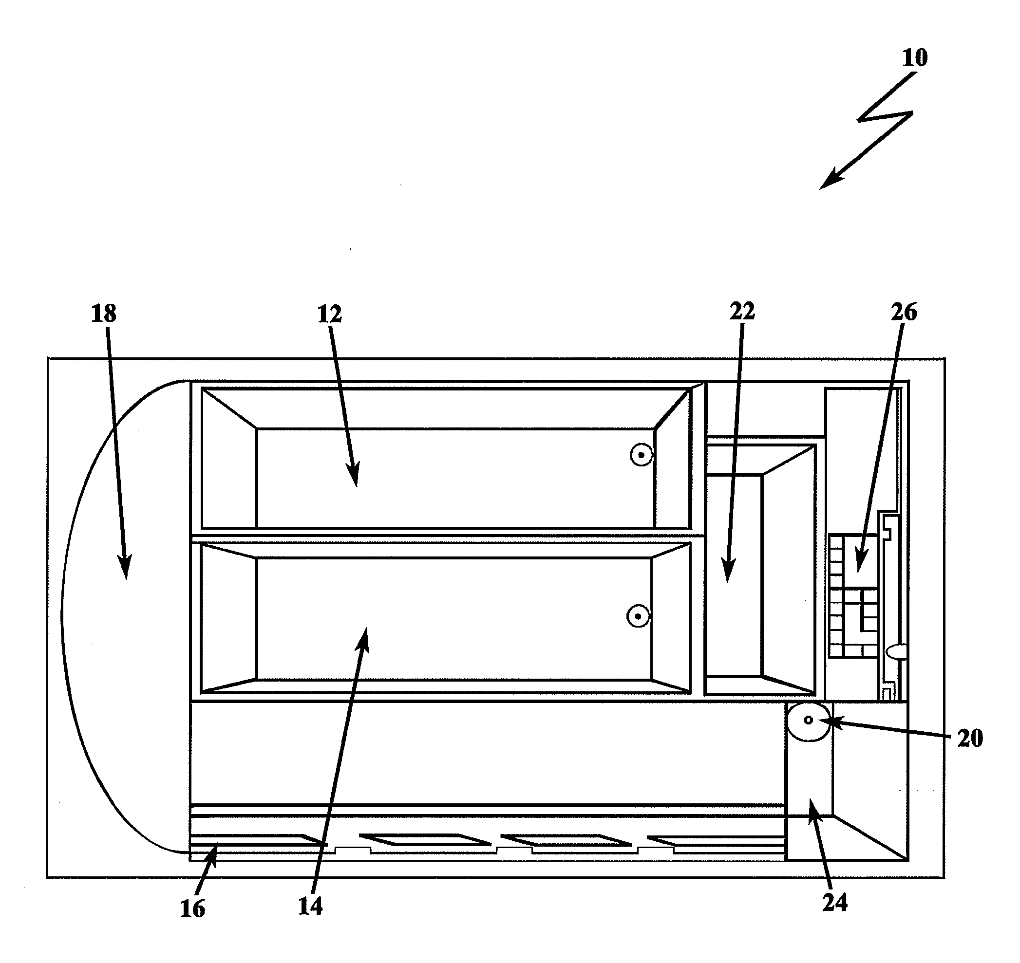
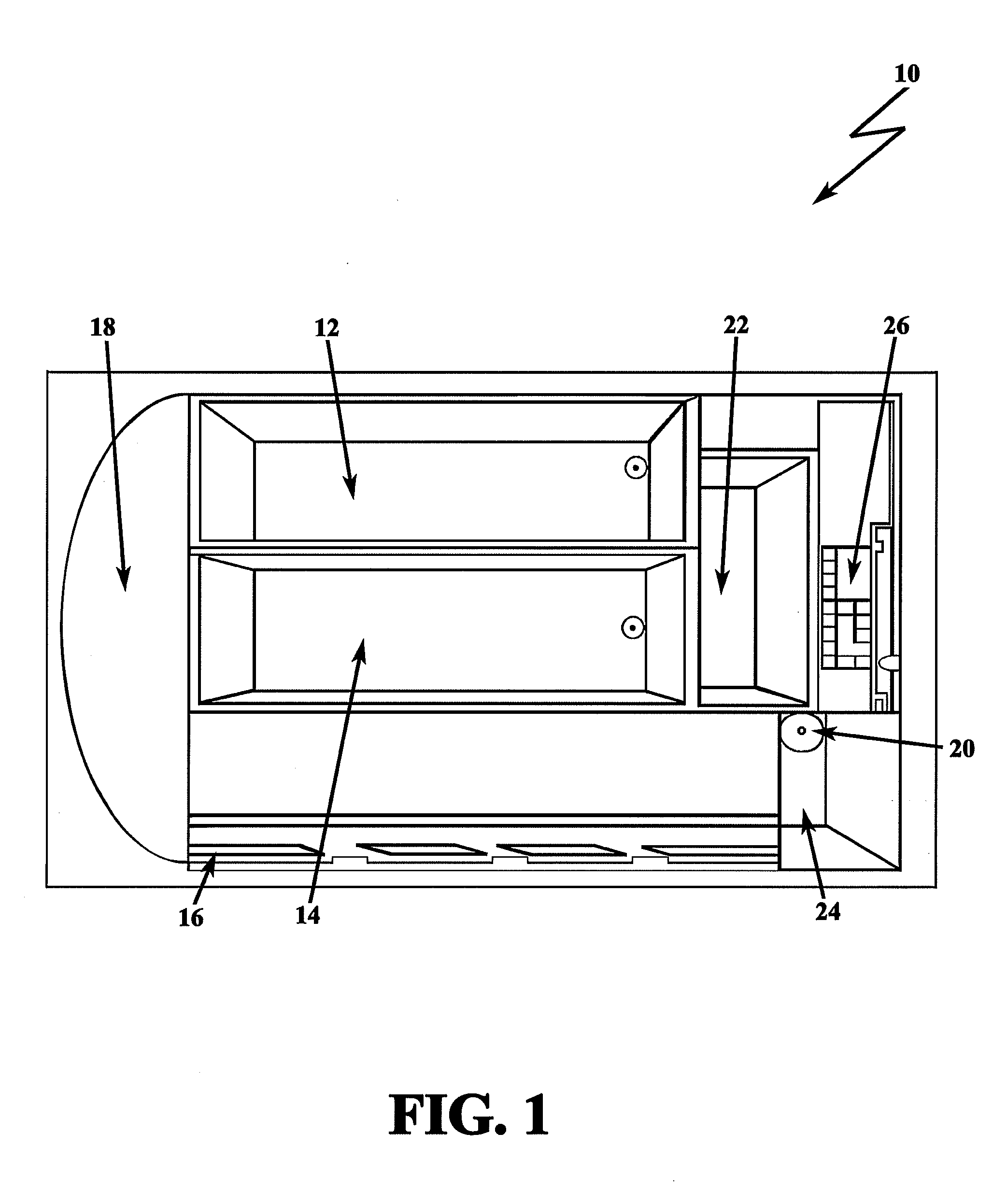
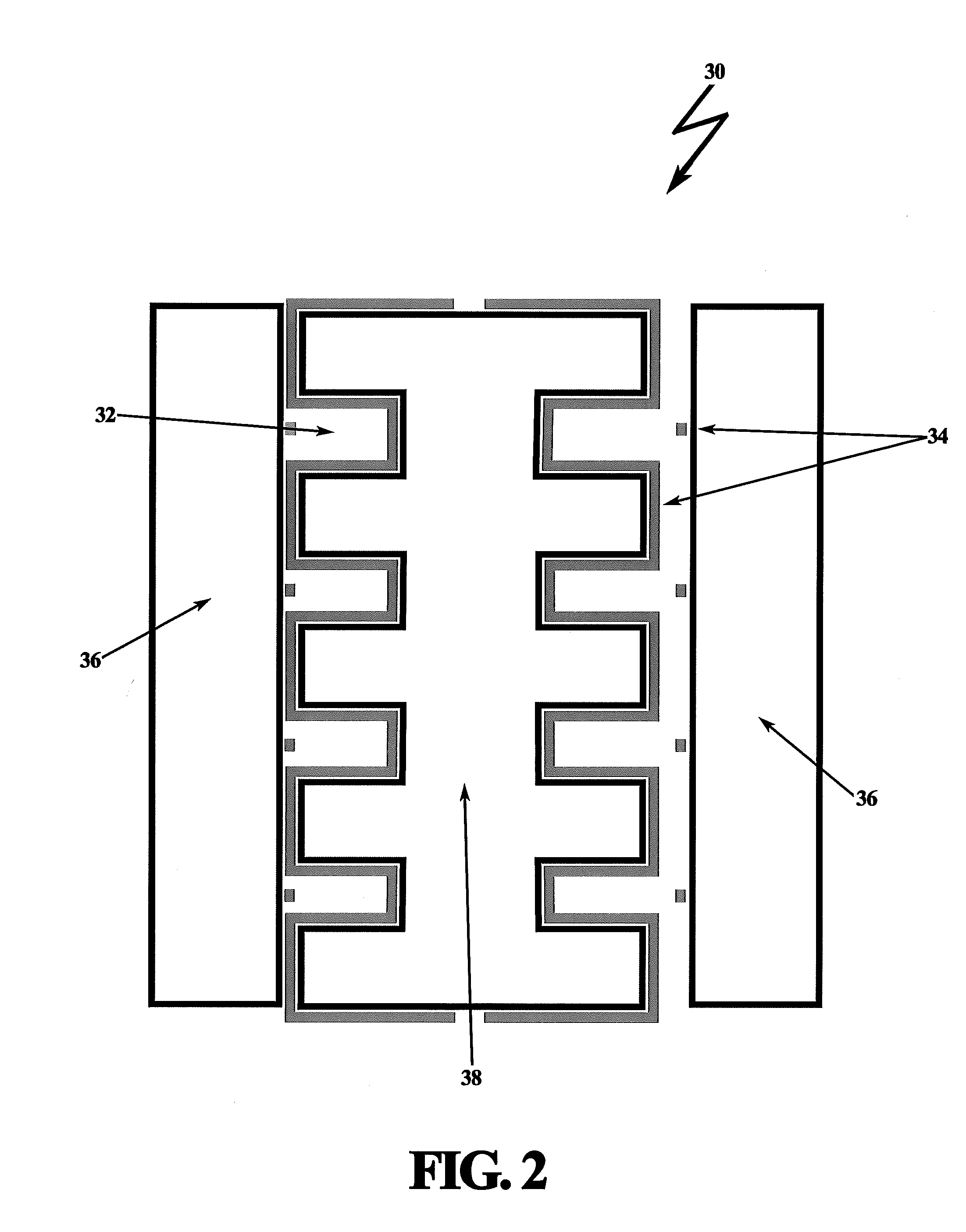
[0074]The filtration system of the present invention performs pathogen detection using a plurality of dielectrophoretic modules of microfluidic channels with distinctive functionality and geometry to obtain separation performance which cannot be obtained in the prior art. Additionally, the present invention integrates a nano-scaled sensor with the filtration system. Advantageously, all components of the filtration system may be embedded, forming an integrated electronic-microfluidic circuit.

[0075]The assembled filtration system automatically transports, separates, condenses, and detects low amounts of particles, cells, and bacteria, or the like, from liquids in a portable configuration that minimizes false positives and negatives.

[0076]The present invention defines a robust method for separa...


PUM

PropertyMeasurementUnit
timeaaaaaaaaaa
dielectrophoretic forceaaaaaaaaaa
voltage potentialaaaaaaaaaa

Abstract

An apparatus for separating an analyte from a test sample, such as bacteria from blood components, based on their dielectric properties, localizing or condensing the analyte, flushing substantially all remaining waste products from the test sample, and detecting low concentrations of the analyte. The module array includes a plurality of microfluidic channels with connecting microfluidic waste channels for directing undesired material away from the analyte. An electric field is applied causing a positive dielectrophoretic force to the analyte to capture the analyte. The electric field is applied to at least one electrode having a plurality of concentric rings or concentric arcs extending radially outwards from a center point, electrically connected to a voltage source such that when voltage is applied to the at least one electrode, the concentric rings or concentric arcs alternate in voltage potential.

Description

BACKGROUND OF THE INVENTION[0001]1. Field of the Invention[0002]The invention relates to an apparatus for pathogen detection. Specifically, the invention relates to the field of pathogen detection systems and diagnostic devices and their micro-component assembly. More specifically, the invention utilizes an apparatus that includes a dielectrophoretic separator, a dielectrophoretic condenser, a dielectrophoretic trap, microfluidic components, and field effect sensor, such as an ion sensitive sensor, nanowire sensor, or nanoribbon sensor configured as biosensors, to perform a pathogen detection process. The invention further relates to a specific electrode design for high yield pathogen and cell capture and separation.[0003]2. Description of Related Art[0004]Bacterial infections cause thousands of diseases in humans and animals every year. Recent deadly outbreaks of E. coli, Salmonella, and Listeria have highlighted the urgent need for more effective methods of detection, identificati...

Claims


Application Information

Patent Timeline
Patent Type & Authority Applications(United States)
IPC IPC(8): G01N27/447G01N27/414
CPCG01N27/44743G01N27/44791G01N27/4145B01L3/502753B03C5/005B03C5/024B01L2300/0874B01L2400/0406B01L2400/0424B01L2400/0487B03C2201/26B03C2201/18
Inventor WEBER, MONIKALO, SIU LUNGMONTANARO OCHOA, HAZAEL FABRIZIOYERINO, CHRISTOPHER DANIELREED, MARK A.
Owner FLUID SCREEN INC
Why Eureka
Try Eureka