Liquid crystal display device

a liquid crystal display and display device technology, applied in static indicating devices, instruments, gas-filled discharge tubes, etc., can solve the problems of difficult to achieve a thinner liquid crystal display and no longer achieve uniform luminan

Inactive Publication Date: 2010-08-05
SHARP KK
View PDF5 Cites 5 Cited by
  • Summary
  • Abstract
  • Description
  • Claims
  • Application Information

AI Technical Summary

Benefits of technology

[0037]According to the arrangement, the surface of the substrate is curved through use of the flexibility of the substrate, and then the plurality of plasma tubes are provided in an array along the surface thus curved. This makes it possible to achieve a backlight whose light emitting s...

Problems solved by technology

This makes it difficult to achieve a thinner liquid crystal display.
In case of reducing, under the circumstances, a thickness ...

Method used


Image

  • Liquid crystal display device
  • Liquid crystal display device
  • Liquid crystal display device

Examples


embodiment 1

[0072]One embodiment of the present invention is described below with reference to the attached drawings. However, the present invention is not limited to the embodiment.

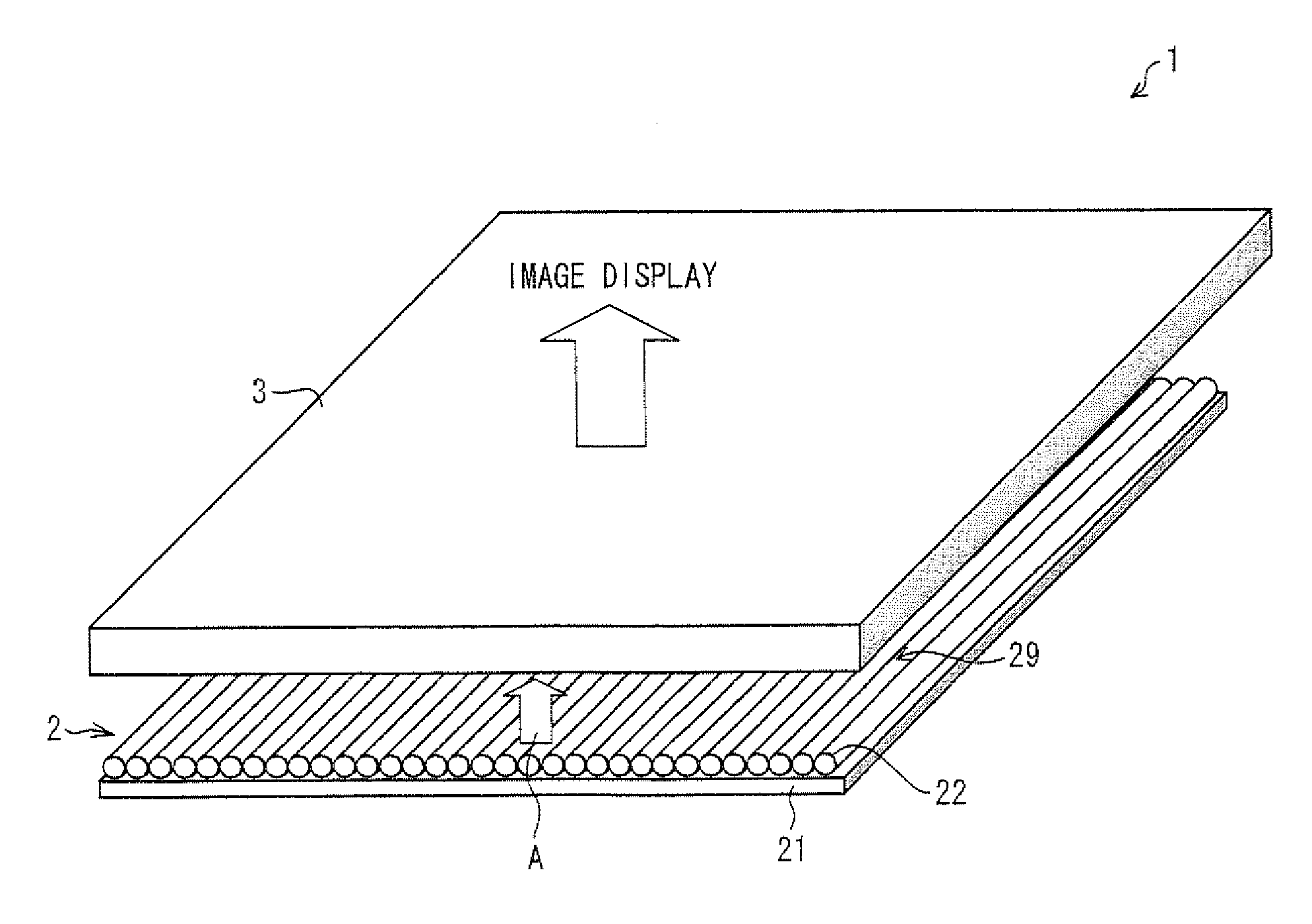
[0073]The present embodiment describes a liquid crystal display device including, as a light source, a backlight in which plasma tubes are employed. FIG. 2 schematically illustrates a structure of a liquid crystal display device 1 including such a backlight.

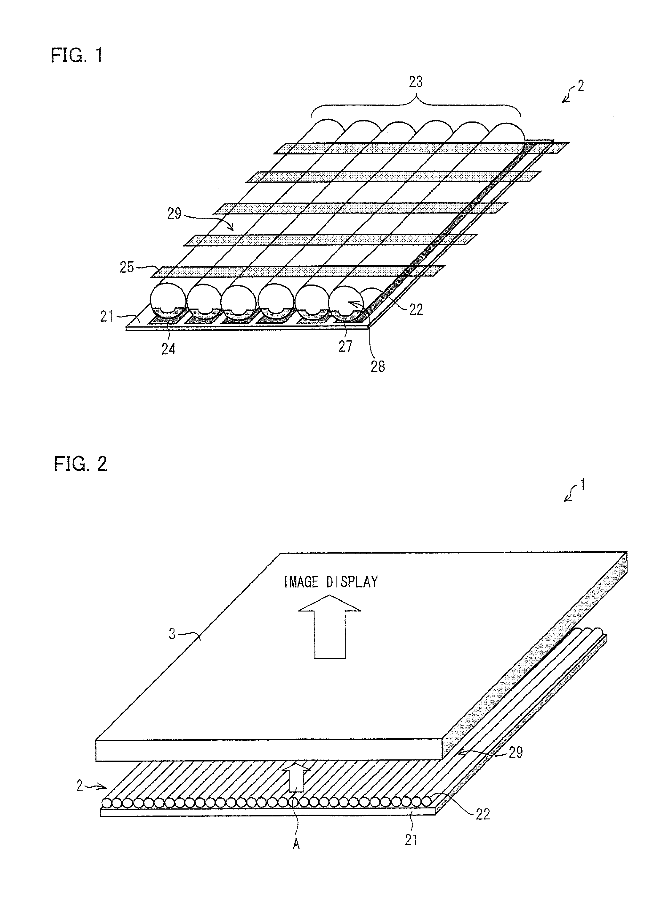
[0074]As illustrated in FIG. 2, the liquid crystal display device 1 of the present embodiment includes (i) a liquid crystal display panel 3 and (ii) a backlight 2 that is provided behind the liquid crystal display panel 3. The backlight 2 is arranged so as to emit light toward the liquid crystal display panel 3. The arrow A in FIG. 2 indicates a direction in which the light is emitted from the backlight 2. The liquid crystal display device 1 is a transmissive liquid crystal display device in which a display is carried out by transmitting the light emitted from th...

embodiment 2

[0098]The second embodiment of the present invention is described below with reference to the attached drawings.

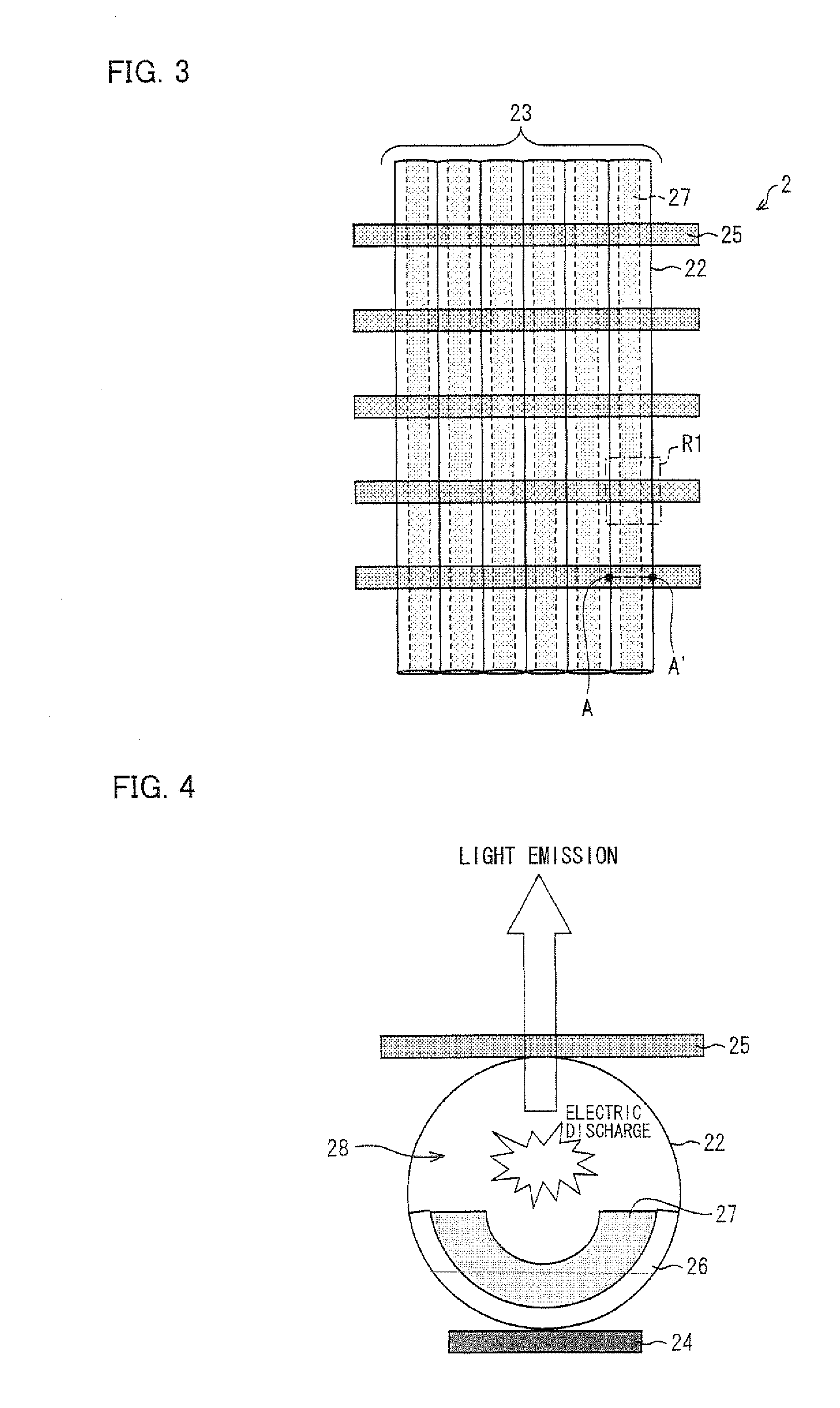
[0099]The first embodiment described a liquid crystal display device including a backlight, in which electric discharge occurs, directly below the upper transparent electrodes 25 in the plasma tubes 22, in response to voltages applied between the lower electrodes 24 and the upper transparent electrodes 25. On the other hand, the second embodiment will describe a liquid crystal display device including a backlight, in which (a) electrodes provided on a light emitting section 29 side of the plurality of plasma tubes 22 constitute electrode pairs 25a (each of which is constituted by a pair of electrodes 25x and 25y) and (b) electric discharge occurs in response to voltages applied between each of the electrode pairs 25a and the lower electrodes 24.

[0100]A liquid crystal display device 1 of the present embodiment has an arrangement similar to that of the liquid crystal display...

embodiment 3

[0116]The third embodiment of the present invention is described below with reference to the attached drawings.

[0117]The first and second embodiments described a liquid crystal display device including a backlight that is arranged such that the lower electrodes 24, which are provided between the substrate 21 and the plurality of plasma tubes 22, are provided for the respective plurality of plasma tubes 22. In contrast, the third embodiment will describe a liquid crystal display device including a backlight that is arranged such that a lower electrode is provided for every predetermined number of plasma tubes (for example, for every three plasma tubes).

[0118]A liquid crystal display device 1 of the present embodiment has an arrangement similar to that of the liquid crystal display device 1 of FIG. 2. Therefore, a description of the liquid crystal display 1 of the present embodiment is omitted here. It should be noted in the following descriptions that members having structures simila...


PUM


Abstract

The liquid crystal display device (1) of the present invention includes a liquid crystal display panel (3) and a backlight (2). In the backlight (2), a plurality of plasma tubes (22) are employed as light sources. The backlight (2) includes: a substrate (21) and; an array structure (23) in which the plurality of plasma tubes (22) are provided, in an array, on the substrate (21). A surface of the array structure (23) opposite to a surface facing the substrate (21) serves as a light emitting section (29) that irradiates the liquid crystal display panel (3). Since the backlight includes plasma tubes serving as the light sources, it is possible to achieve a thinner liquid crystal display device that carries out a high-definition image display in spite of its thin thickness.

Description

TECHNICAL FIELD[0001]The present invention relates to a liquid crystal display device. The present invention particularly relates to a liquid crystal display device employing plasma tubes as a backlight.BACKGROUND ART[0002]A liquid crystal display device has become rapidly widespread recently in place of a cathode ray tube (CRT) display device. Such a liquid crystal display device is for widely use in an electronic device such as a liquid crystal display television, a monitor, or a mobile phone, because the liquid crystal display device has the advantages that it is energy-saving, thin, and light. It is possible to further put such advantages to good use by, for example, improving a backlight, which is provided behind the liquid crystal display device.[0003]The backlight is broadly classified into a side backlight (also called “edge backlight”) and a direct backlight. The side backlight is arranged such that (i) a light guide member is provided behind a liquid crystal display panel ...

Claims


Application Information

Patent Timeline
IPC IPC(8): G09G3/36H01J17/49
CPCG02F1/133604G02F2001/133614H01J65/046H01J17/485H01J61/92H01J11/00G02F1/133614
Inventor NISHIHARA, YUSUKEKUBO, MASUMITAGUCHI, TOKIOOKAMOTO, KENJI
Owner SHARP KK
Why Eureka
Try Eureka