
Surface light source and electrically illuminated signboard

a technology of electrical illumination and light source, which is applied in the direction of lighting and heating apparatus, instruments, display means, etc., can solve the problems of inability to achieve perfect uniformity in a surface, inability to obtain light source of a large type, and enlarging of television receivers or the like, so as to improve color rendering properties, uniform brightness, and thin backlight

Inactive Publication Date: 2009-04-14
ZYCC +1
View PDF8 Cites 7 Cited by
  • Summary
  • Abstract
  • Description
  • Claims
  • Application Information

AI Technical Summary

Benefits of technology

[0010]Another object of the present invention is to provide an electrically illuminated signboard with low electric power consumption, which is thin and which displays uniformly even in the electrically illuminated signboard displaying a large display panel.
[0021]The surface light source can display with good appearance and excellent color rendering property when used in liquid crystal display devices of a thin type by setting an inclined angle and a height of the side walls of the box body so that lights of the semiconductor light emitting devices provided on at least two corners are mixed mutually in the box body by being reflected diffusedly on the bottom surface and the side walls of the box body, and that the light of the semiconductor light emitting devices provided on at least two corners is averaged in brightness, chromaticity and luminescent hue.
[0022]The surface light source can irradiate the light having almost uniform brightness on the entire surface without making any gaps between the surface light source units by wiring or the like, by drawing out leads to be connected to electrodes of each of the light emitting devices in a space portion formed outside of the box body at a bottom between adjacent box bodies, and by connecting the leads to a power source.
[0025]By the present invention, since a light diffused-reflection member reflecting light diffusedly is provided on an inner surface of the box body, and since semiconductor light emitting devices are provided in the bottom surface so as to irradiate the light toward side walls, almost a half of an amount of the light spread by the directionality of the light emitting devices is reflected diffusedly by the bottom surface, and the light traveling straight is reflected by the side walls. Then, lights from each of the light emitting devices are mixed mutually in the box body, because the light from each of the light emitting devices arranged on the corners of the bottom surface of the box body is reflected diffusedly in a same manner. Therefor, if some variance of the brightness and the chromaticity of the semiconductor light emitting devices exists, the chromaticity of each of the LEDs does not appear partially like in the right-under type, by leveling the variance. As a size of the box body can be set arbitrarily in a range from 30 to 130 mm, in case of adjusting brightness of light sources partially (each area), for example, in liquid crystal television receivers, the brightness of every box body can be adjusted, a remarkably finer adjustment can be carried out than an adjustment in elongated cold cathode ray tubes by the prior art and quality of displayed images can be raised as a result.
[0026]Since the box body is formed in a structure in which the side walls incline and spread outward, spaces are formed at a bottom surface side between adjacent box bodies in tiling a number of box bodies while the box bodies are arranged without any gap at a surface side from which the light is irradiated. And since the light emitting devices are provided on the corners of the bottom surface of the box bodies, a power source can be connected to leads to drive the light emitting device by laying leads outside of the bottom surface of the box bodies or can be connected directly to wiring of a circuit board on which the bottom surface of the box body is fixed. Then, as the power source can be connected easily to each of the light emitting devices while the brightness is uniform without any gap at the surface side, even if any number of body boxes are arranged, even a light source for a large screen can irradiate light simply and with uniform brightness. If, it is preferable that the box body is quadrilateral in case of a quadrilateral screen such as those of liquid crystal television receivers or electrically illuminated signboards, because tiling is carried out without waste and simply, but tiling can be carried out in other polygons in a same manner.
[0028]As a result, even in liquid crystal television receivers of a large type, a light source can be obtained in which: a thin backlight with uniform brightness can be realized; the brightness can be controlled for each of surface light source units; the brightness or the like of backlight can be controlled for each of areas; and not only improvement of color rendering property but also display of images with more excellent quality than that of the cold cathode ray tube can be achieved. In addition, even in electrically illuminated signboards, a signboard with low electricity consumption, long life time and maintenance free, by using semiconductor light emitting devices can be obtained.

Problems solved by technology

In recent years, liquid crystal display devices are used as display screens, being accompanied with thinning of monitors for television receivers, personal computers or the like, and furthermore the television receivers or the like have a tendency of enlarging.
In the former case, although brightness in almost entire surface can be uniformed by the light guide plate in a liquid crystal panel of a small type having a side of, for example, approximately 50 mm or less, a light source of a large type can not be obtained without arranging a number of the light guide plates because uniformity in a surface can not be achieved perfectly in the liquid crystal display devices having a screen larger than that described above.
Namely, a surface light source of a desired size can not be obtained by arranging (tiling) a number of light guide plates.
Furthermore, there occurs a problem that uniform chromaticity can not be obtained, since chromaticity of each LED varies even among white LEDs and since a distance to the light diffusion member 114 should be larger because lights are not mixed perfectly in case of making white light by mixing colors by using each of LEDs of R, G, and B.
In case of using LEDs for the light sources, there rise same problems as that in backlights for liquid crystal display devices as described above.
Uniform irradiation from an entire surface by diffusing the light in the light guide plate is hardly obtained because the light is apt to travel straight even if it is made easy to introduce the light into the light guide plate by using LEDs of a dome type and by narrowing directionality of the light.
Therefor, the light emitted from the LEDs can not be utilized efficiently, and there exists a problem that the surface light source of high brightness, uniformity and a large type can not be obtained.
In LEDs of a chip type not in LEDs of a dome type, a surface light source of high brightness and a large type has not been achieved because of small amount of light flux and its indirect light.
After all, there are problems that in a conventional surface light source using LEDs, a surface light source of a large type can not be obtained simply by using a light guide plate, and that in the right-under type of arranging the LEDs directly under a display plate in matrix structure, thinning the surface light source can not be achieved because a means for dispersing heat becomes necessary as output power of the LEDs is increased to make a distance from a position of the LEDs to a light diffusion member large.
Further, in the right-under type, there rises still a problem that a production cost is raised significantly, since LEDs of certain brightness and chromaticity should be used by selecting the LEDs because the lights of each of the LEDs can be hardly mixed.

Method used


Image

  • Surface light source and electrically illuminated signboard
  • Surface light source and electrically illuminated signboard
  • Surface light source and electrically illuminated signboard

Examples


Embodiment Construction

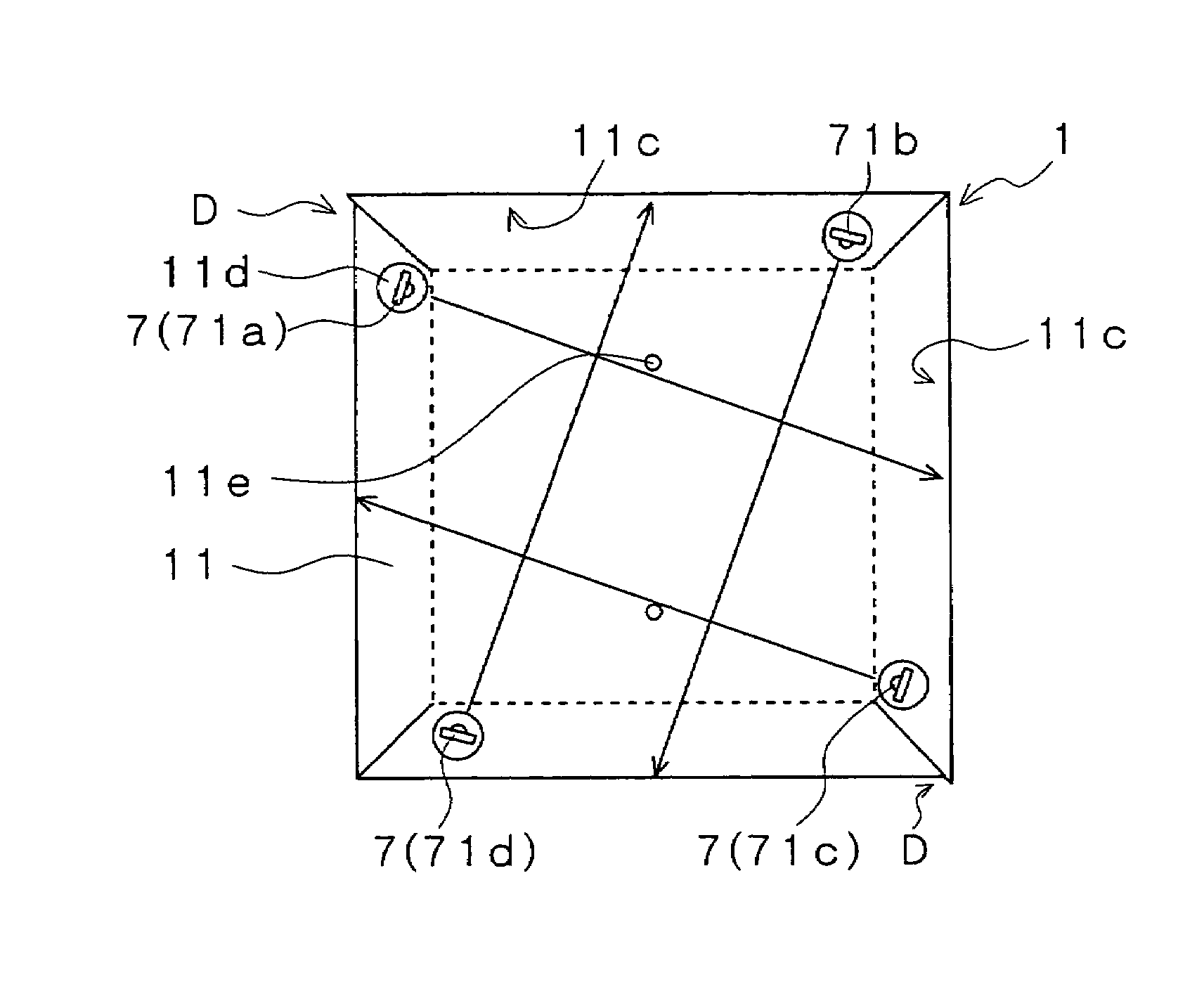
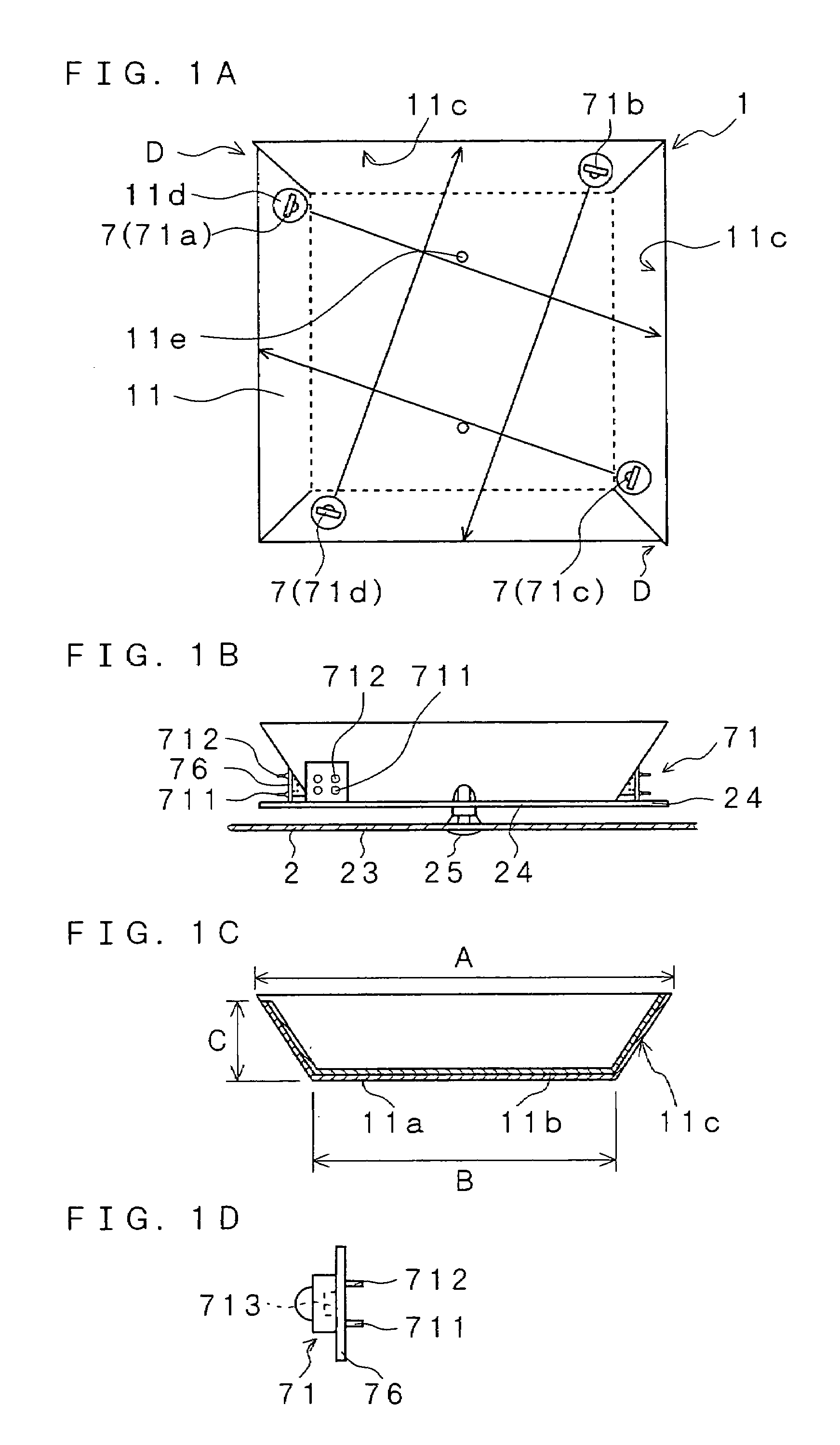
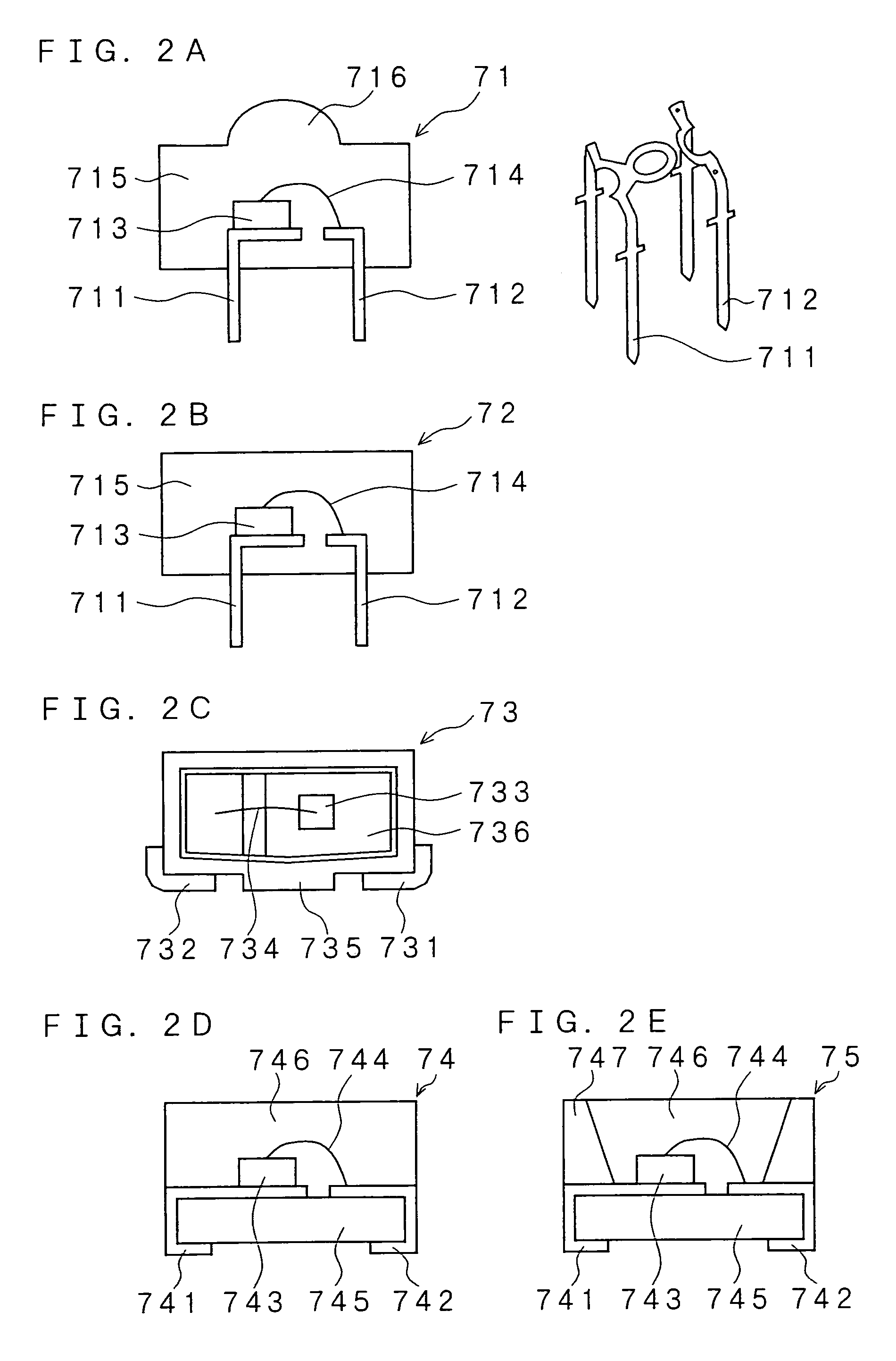
[0043]An explanation will be given below of a surface light source according to the present invention and an electrically illuminated signboard using the same in reference to the drawings. As there are shown in FIGS. 1A to 1D, figures explaining a plan view and a side view of an embodiment of the surface light source unit according to the present invention, a cross-sectional view of the box body and a side view of a light emitting device, the surface light source unit according to the present invention is provided with LEDs 7 of a chip type provided on at least opposite two corners of the bottom surface of the box body 11 of a tray shape so as to irradiate inside of the box body, whose bottom surface is quadrilateral, whose upper side is open, on an inner surface of which a light diffused-reflection member 11b is provided, and whose side walls 11c are inclined outward. Here, a plurality of LEDs 7 (71) are arranged so that a region irradiated by each of the LEDs 7 (71) rotates in a c...


PUM


Abstract

LEDs (7) are arranged on at least opposite two corners of a bottom surface of a box body (11) of a tray shape whose bottom surface is quadrilateral, whose upper side is open, on an inner surface of which a light reflection member (11b) is provided, and whose side walls (11c) are inclined outward, so as to irradiate inside of the box body, wherein a plurality of LEDs (71) are arranged so that a region irradiated by each of the LEDs (71) rotates sequentially in a specific direction (same direction). As a result, there can be obtained a surface light source having high brightness and uniformity in an arbitrary size whether the light source is small or large while using semiconductor light emitting devices (LEDs), and an electrically illuminated signboard using the surface light source, which is thin and capable of uniform display and which operates with low electricity consumption.

Description

FIELD OF THE INVENTION[0001]The present invention relates to a surface light source used as backlights of liquid crystal display devices, illuminations of electrically illuminated signboards, or the like and relates to an electrically illuminated signboard using the same. More particularly, the present invention relates to a surface light source capable of uniforming brightness and chromaticity on its surface, which can be used for backlights of liquid crystal display devices such as television receivers of a thin and large type, or the like, while using semiconductor light emitting devices (LEDs) for light sources, and relates to an electrically illuminated signboard using the same.BACKGROUND OF THE INVENTION[0002]In recent years, liquid crystal display devices are used as display screens, being accompanied with thinning of monitors for television receivers, personal computers or the like, and furthermore the television receivers or the like have a tendency of enlarging. Cold catho...

Claims


Application Information

Patent Timeline
Patent Type & Authority Patents(United States)
IPC IPC(8): G09F13/04
CPCG02F1/133603G02F1/133605G02F1/133611
Inventor SAKAI, YOSHIHIRO
Owner ZYCC
Learn More