
Backlight including patterned reflectors, diffuser plate, and method for fabricating the backlight

a backlight and reflector technology, applied in the field of backlights including patterned reflectors, can solve the problems of undesirable optical loss and high overall display thickness, and achieve the effects of improving light efficiency, improving the ability to hide light sources, and thin backlights

Active Publication Date: 2021-12-23
CORNING INC
View PDF9 Cites 4 Cited by
  • Summary
  • Abstract
  • Description
  • Claims
  • Application Information

AI Technical Summary

Benefits of technology

The patent describes thin direct-lit backlights that use less light, reducing the thickness of the display. These backlights also hide the light sources, resulting in a more uniform brightness across the entire display. This improves the quality of the display and reduces the need for additional lighting.

Problems solved by technology

The optical distance (OD) between the LEDs and the diffuser plate or film in such configurations (e.g., from at least 10 to typically about 20-30 millimeters), however, still results in an undesirably high overall display thickness and / or these configurations may produce undesirable optical losses as the backlight thickness is decreased.

Method used


Image

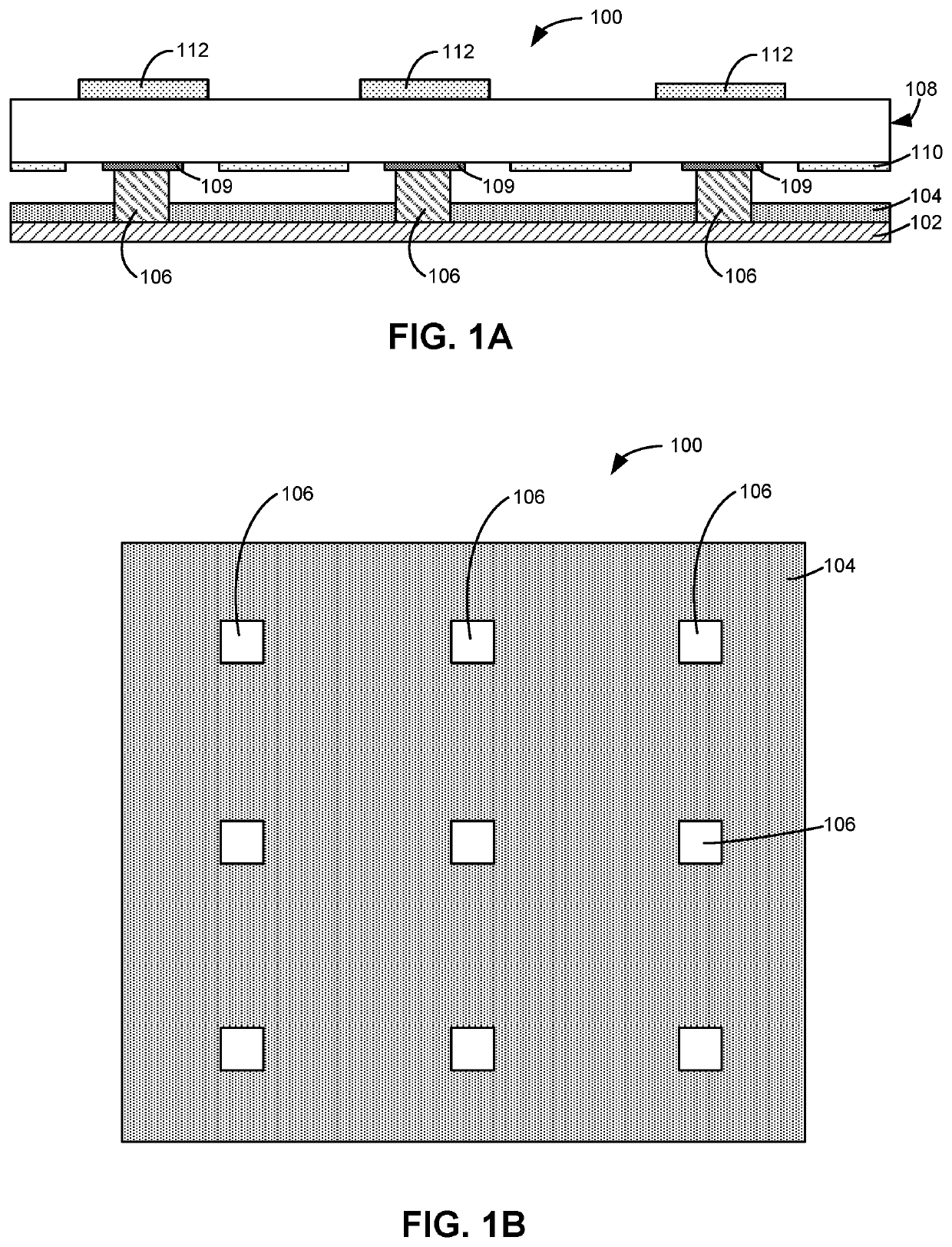
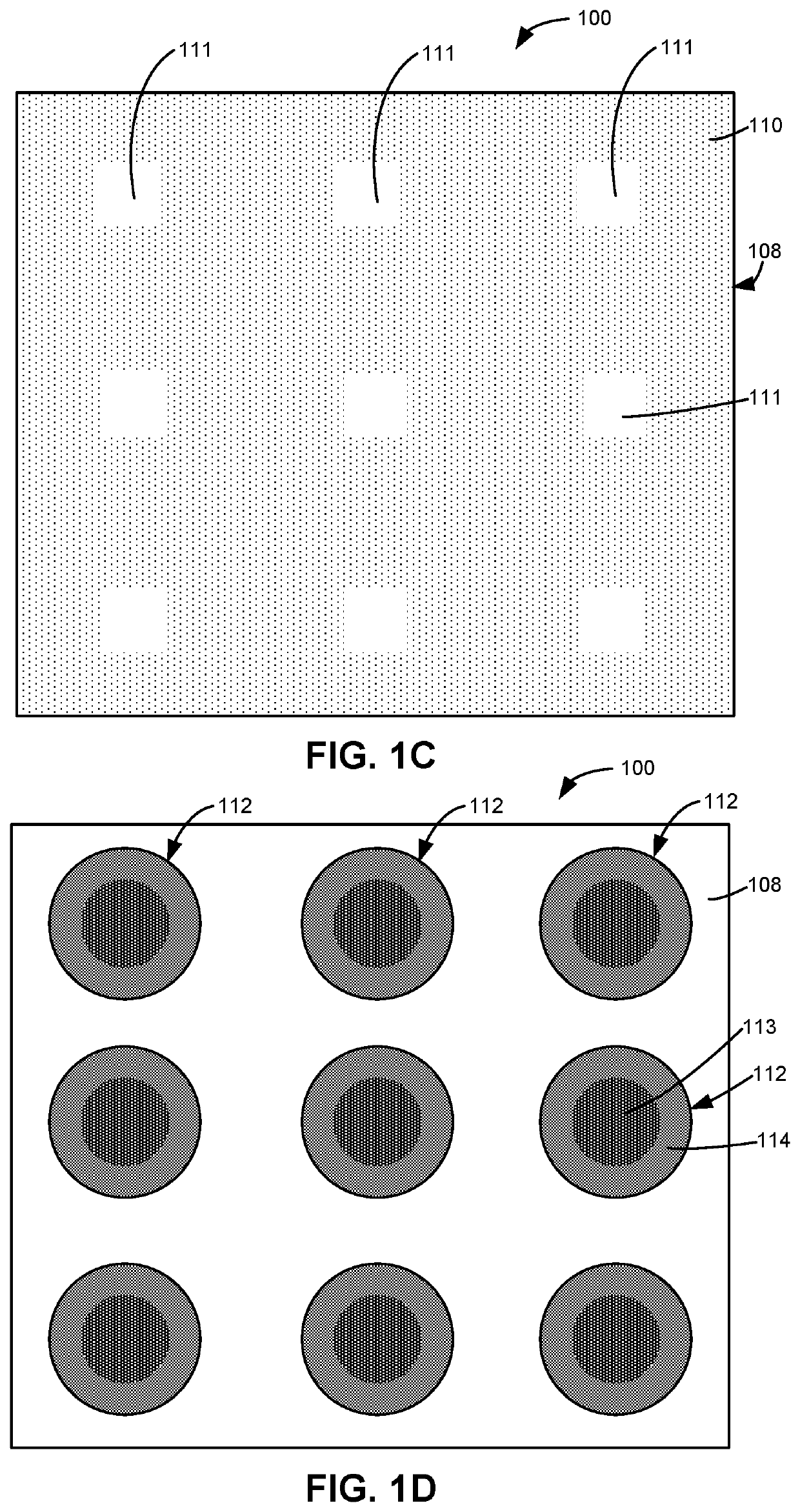
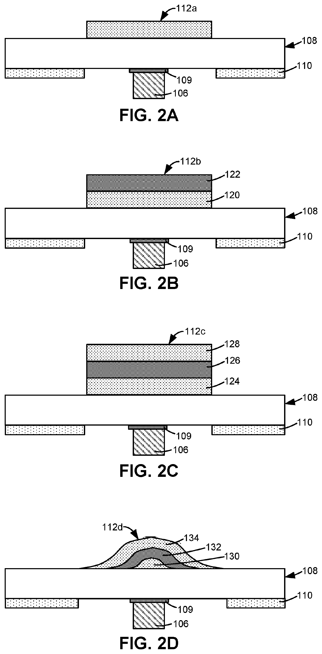
  • Backlight including patterned reflectors, diffuser plate, and method for fabricating the backlight
  • Backlight including patterned reflectors, diffuser plate, and method for fabricating the backlight
  • Backlight including patterned reflectors, diffuser plate, and method for fabricating the backlight

Examples


Embodiment Construction

[0048]Reference will now be made in detail to embodiments of the present disclosure, examples of which are illustrated in the accompanying drawings. Whenever possible, the same reference numerals will be used throughout the drawings to refer to the same or like parts. However, this disclosure may be embodied in many different forms and should not be construed as limited to the embodiments set forth herein.

[0049]Ranges can be expressed herein as from “about” one particular value, and / or to “about” another particular value. When such a range is expressed, another embodiment includes from the one particular value and / or to the other particular value. Similarly, when values are expressed as approximations, by use of the antecedent “about,” it will be understood that the particular value forms another embodiment. It will be further understood that the endpoints of each of the ranges are significant both in relation to the other endpoint, and independently of the other endpoint.

[0050]Dire...


PUM

PropertyMeasurementUnit
Transmittance Distributionaaaaaaaaaa
hazeaaaaaaaaaa
thicknessaaaaaaaaaa

Abstract

A backlight includes a substrate, a plurality of light sources, a reflective layer, a light guide plate, a pattern of light extractors, a plurality of patterned reflectors, and a diffusive layer. The plurality of light sources are proximate the substrate. The reflective layer is on the substrate. The light guide plate is proximate the plurality of light sources. The pattern of light extractors is on the light guide plate. The plurality of patterned reflectors are on the light guide plate. Each patterned reflector is aligned with a corresponding light source. The diffusive layer is on the light guide plate.

Description

[0001]This application claims the benefit of priority under 35 U.S.C. § 365 of International Patent Application Serial No. PCT / RU2019 / 000722, filed on Oct. 9, 2019, International Patent Application Serial No. PCT / RU2019 / 000250, filed on Apr. 15, 2019, and International Patent Application Serial No. PCT / RU2018 / 000738, filed on Nov. 12, 2018, the content of each are relied upon and incorporated herein by reference in their entirety.BACKGROUNDField[0002]The present disclosure relates generally to backlights for displays. More particularly, it relates to backlights including patterned reflectors.Technical Background[0003]Liquid crystal displays (LCDs) are commonly used in various electronics, such as cell phones, laptops, electronic tablets, televisions, and computer monitors. LCDs are light valve-based displays in which the display panel includes an array of individually addressable light valves. LCDs may include a backlight for producing light that may then be wavelength converted, fi...

Claims


Application Information

Patent Timeline
Patent Type & Authority Applications(United States)
IPC IPC(8): G02F1/13357G02B5/02G02F1/1335
CPCG02F1/133606G02F1/133524G02B5/02G02B5/0205G02B17/002G02B17/0668G02B6/0055G02B6/0031G02B6/0043G02B6/0061G02B6/0068G02F1/133605G02F1/133614G02B6/0051G02B5/0242G02B6/0065G02F1/1334G02F1/1335
Inventor ALLEN, KIRK RICHARDKISELEV, FEDOR DMITRIEVICHKUKSENKOV, DMITRI VLADISLAVOVICHLYNN, CHRISTOPHER MICHAELMAUREY, PAMELA ARLENEMI, XIANG-DONGPOLLARD, SCOTT CHRISTOPHERTIMOFEEV, NIKOLAY TIMOFEYEVICHVARANYTSIA, ANDRII
Owner CORNING INC
Learn More