
Light-emitting device, illuminating device comprising same, and liquid crystal display

a technology of light-emitting devices and illuminating devices, which is applied in the direction of lighting support devices, lighting and heating apparatus, instruments, etc., can solve the problem of even larger regions, and achieve the effects of thin liquid crystal display, thin backlight, and low heigh

Inactive Publication Date: 2012-08-07
SHARP KK
View PDF6 Cites 3 Cited by
  • Summary
  • Abstract
  • Description
  • Claims
  • Application Information

AI Technical Summary

Benefits of technology

The present invention provides a light-emitting device with a low height that allows for a thinner backlight and liquid crystal display. The device includes a film with LEDs arranged in line on it and a conductor region on the film to connect the LEDs to an LED driver. The film is bent along a division line between the LED mounting region and the conductor region. The invention also includes an illuminating device with the light-emitting device and a light guide plate through which the light emitted from the light-emitting device propagates to be emitted from the light emitting surface of the light guide plate. The invention also provides a liquid crystal display with the illuminating device. The invention allows for a flexible arrangement of LEDs and improved brightness, while keeping the height of the device to a minimum. A reflective material can be added to enhance the light emitted by the LEDs. A support member can be provided to keep the device stable.

Problems solved by technology

Furthermore, when a connector is provided, this region becomes even larger.

Method used


Image

  • Light-emitting device, illuminating device comprising same, and liquid crystal display
  • Light-emitting device, illuminating device comprising same, and liquid crystal display
  • Light-emitting device, illuminating device comprising same, and liquid crystal display

Examples


first preferred embodiment

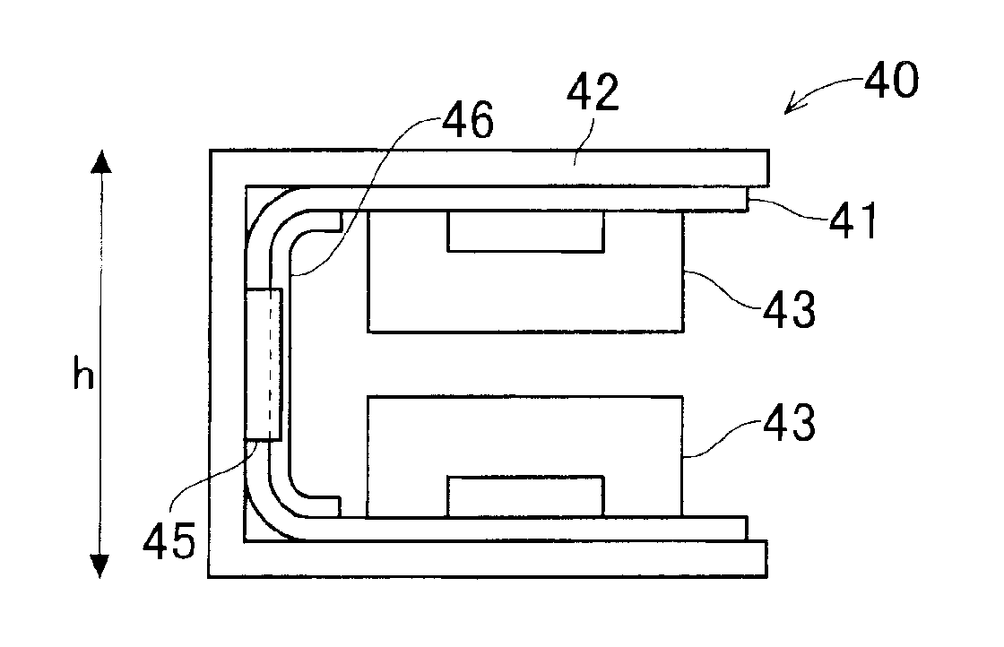
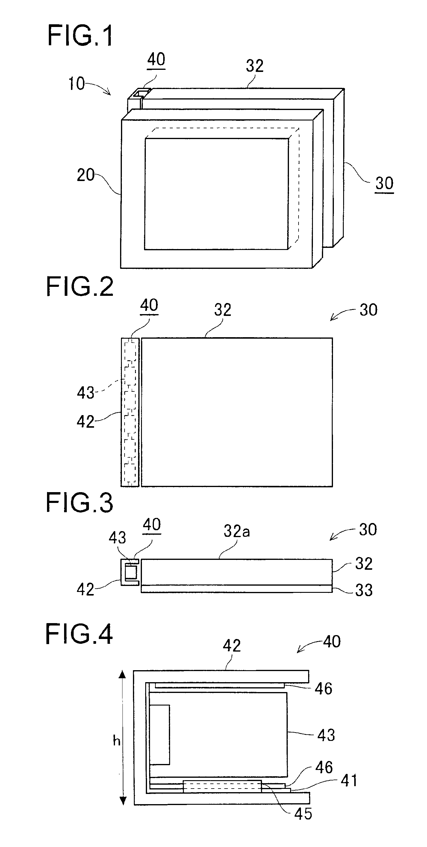
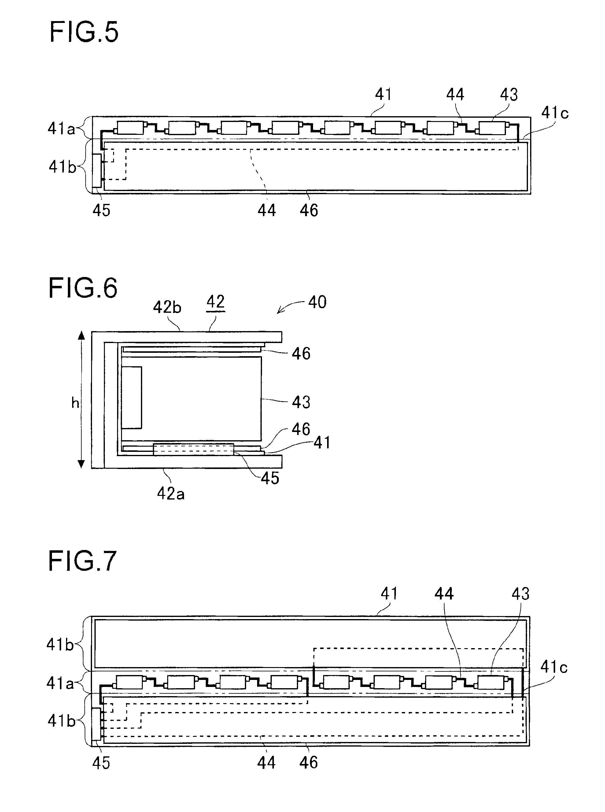
[0037]A description will be given of a first preferred embodiment of the present invention with reference to the accompanying drawings. FIG. 1 is a diagram schematically showing the structure of a liquid crystal display of the first preferred embodiment, FIG. 2 is a plan view showing a backlight of the first preferred embodiment, FIG. 3 is a front view showing the backlight, FIG. 4 is a front view showing a light-emitting device of the first preferred embodiment, and FIG. 5 is a developed view showing a film of the first preferred embodiment of the present invention.

[0038]As shown in FIG. 1, the liquid crystal display 10 is provided with a liquid crystal panel 20 and a backlight 30 that serves as an illuminating device. The liquid crystal panel 20 is provided with a TFT substrate, a counter substrate, and liquid crystal held between the TFT substrate and the counter substrate. The liquid crystal panel 20 displays an image by controlling the alignment of the liquid crystal by applyin...

second preferred embodiment

[0049]Next, a description will be given of a second preferred embodiment of the present invention with reference to the accompanying drawings. FIG. 9 is a developed view showing a film of the second preferred embodiment, and FIG. 10 is a front view of a light-emitting device of the second preferred embodiment. The second preferred embodiment has the same structure as the first preferred embodiment except that the LEDs are arranged on the film in a different manner, and the parts and components that are substantially the same as those in the first preferred embodiment are identified with the same reference numerals.

[0050]As shown in FIG. 9, a film 41 of this preferred embodiment is formed of a conductor region 41b and two LED mounting regions 41a between which the conductor region 41b is sandwiched. A plurality of LEDs 43, which are connected to one another by a conductor 44, are arranged on each of the LED mounting regions 41a. The conductors 44, no matter which one of the LED mount...


PUM


Abstract

In a light emitting device, LEDs are arranged in a line on a film which is provided with a conductor. The conductor connects the LEDs to a connector. The film is bent at a division line between a region where the LEDs are arranged and a region where the conductor is formed, and disposed on the inner surface of a reflector. A reflective material is arranged on a surface of the conductor region which faces to the LEDs.

Description

BACKGROUND OF THE INVENTION[0001]1. Field of the Invention[0002]The present invention relates to an elongated light-emitting device including an LED, an illuminating device using the elongated light-emitting device as a backlight, and a liquid crystal display including the illuminating device.[0003]2. Description of the Related Art[0004]Recently, display devices using a liquid crystal panel, which is thinner than a CRT (cathode ray tube), have been widely used. The liquid crystal panel, not emitting light itself, displays an image by using external light or by being irradiated with light from an illuminating device.[0005]Examples of illuminating devices for use in liquid crystal displays include the sidelight type backlight proposed in JP-A-2004-21147 (pages 4 and 5, FIG. 1). This sidelight type backlight is used by being placed behind a liquid crystal panel, and is formed of a flat plate called a light guide plate formed of acrylic resin and a light-emitting device that is placed a...

Claims


Application Information

Patent Timeline
Patent Type & Authority Patents(United States)
IPC IPC(8): F21V7/04
CPCG02B6/0031G02B6/0068G02B6/0083H05K1/189G02B6/0073G02F1/133615H05K2201/047H05K2201/10106H05K2201/2054
Inventor HAMADA, TETSUYA
Owner SHARP KK
Learn More