

Ink jet print head
a jet print head and jet jet technology, applied in printing and other directions, can solve the problems of lowering the print grade, ejecting ink to fly in an inclined direction, and the difference in flow resistance between ink channels
- Summary
- Abstract
- Description
- Claims
- Application Information
AI Technical Summary
Benefits of technology
Problems solved by technology
Method used
Image

Examples
first embodiment
[0040]A first embodiment of the present invention will be described below with reference to the drawings.
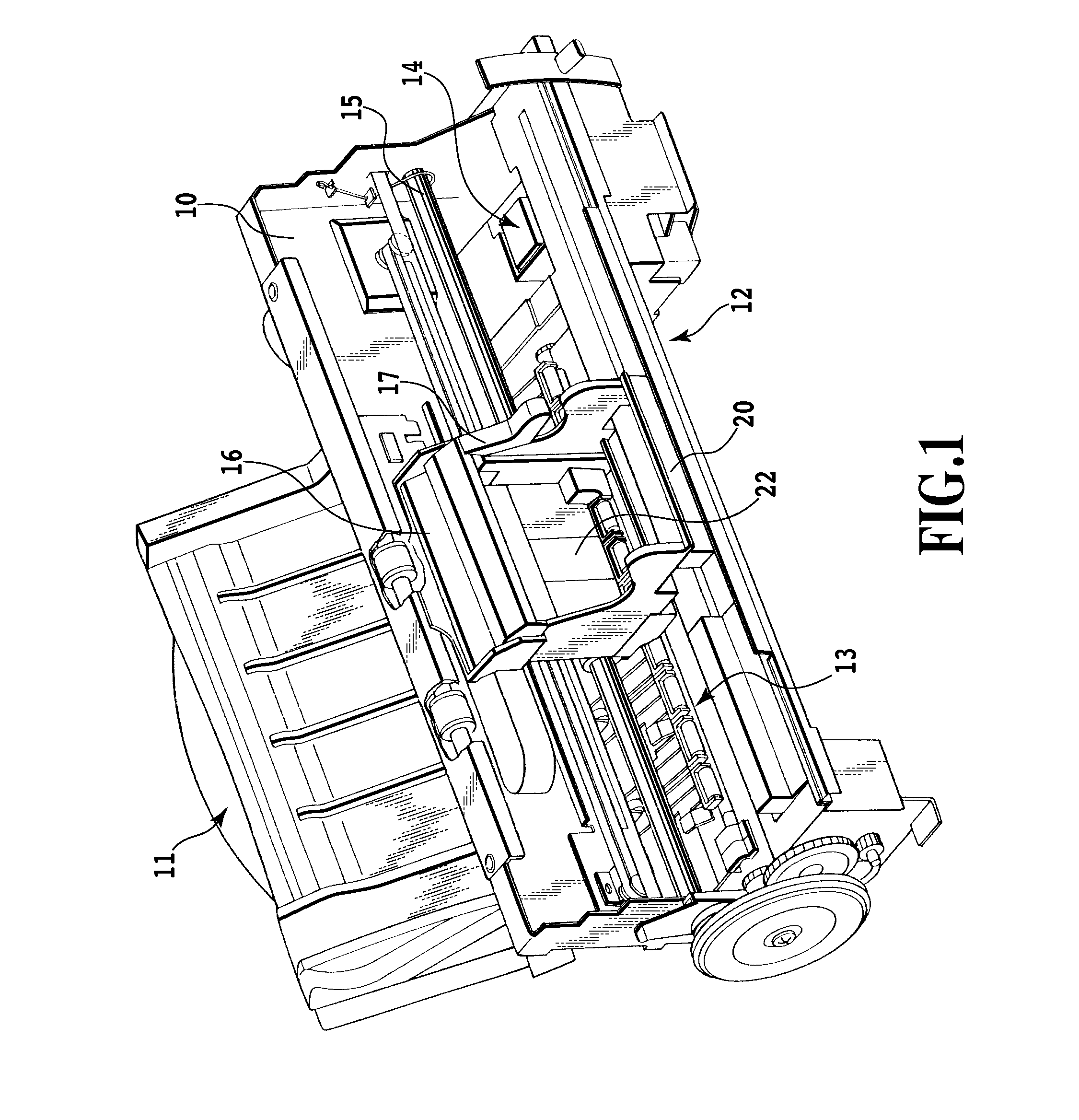
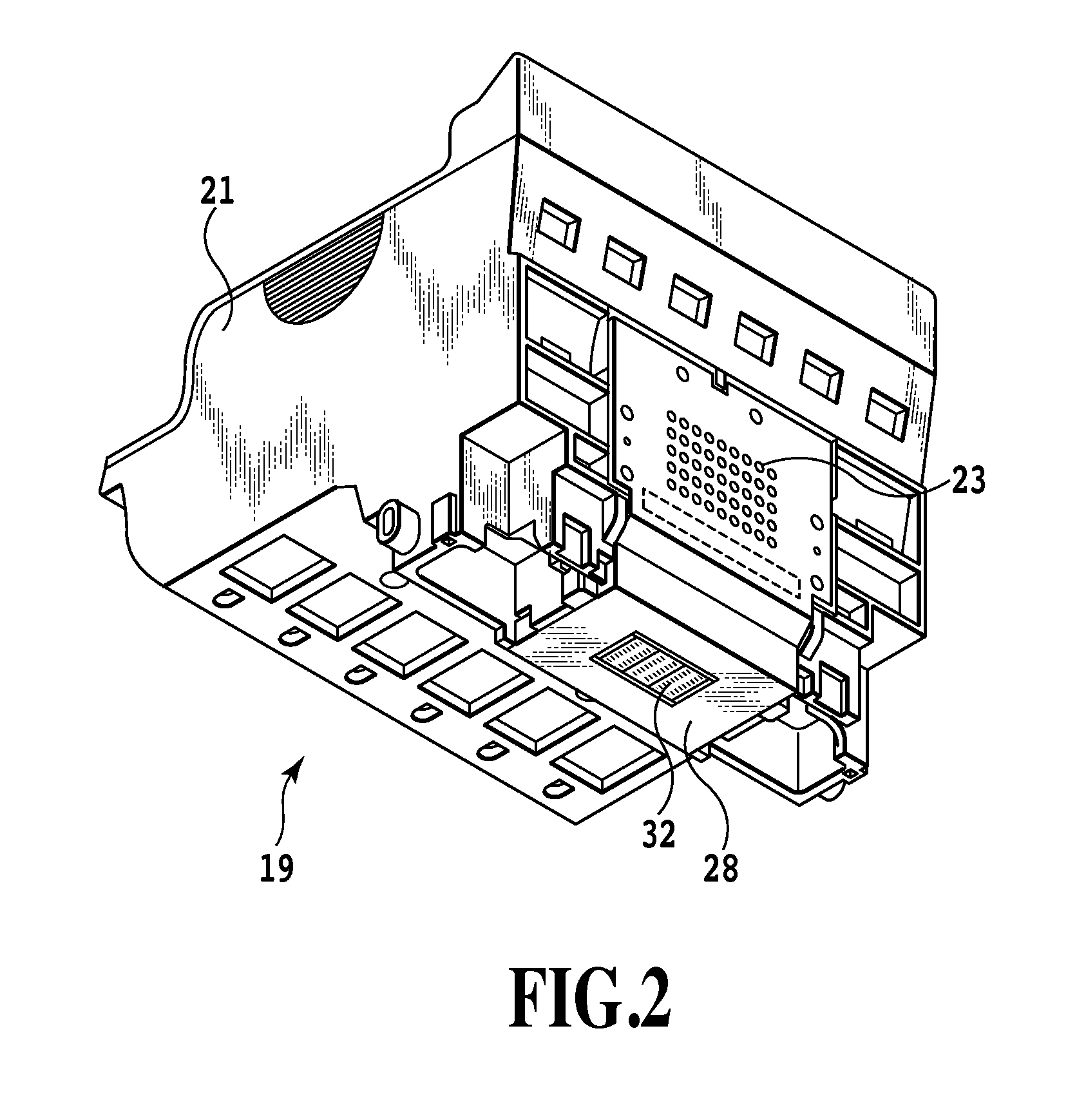
[0041]FIG. 1 is a diagram showing the appearance of a mechanism portion of an ink jet print apparatus to which an ink jet print head according to the present embodiment is applicable. FIG. 2 is a diagram showing the appearance of a head cartridge used in the ink jet print apparatus in FIG. 1. Moreover, FIG. 3 is a diagram showing the appearance of an ink jet print head in the head cartridge'. A chassis 10 of the ink jet print apparatus according to the present embodiment comprises a plurality of plate-like metal members with a predetermined rigidity. The chassis 10 forms the framework of the ink jet print apparatus. The chassis 10 includes a medium feeding section 11 configured to feed a sheet-like print medium (not shown in the drawings) to the interior of the ink jet print apparatus. The chassis 10 further includes a medium conveying section 13 configured to guide the print med...
second embodiment
[0062]A second embodiment of the present invention will be described below with reference to the drawings. The basic configuration of the present embodiment is similar to that of the first embodiment. Thus, only the characteristic arrangements of the present embodiment will be described below.
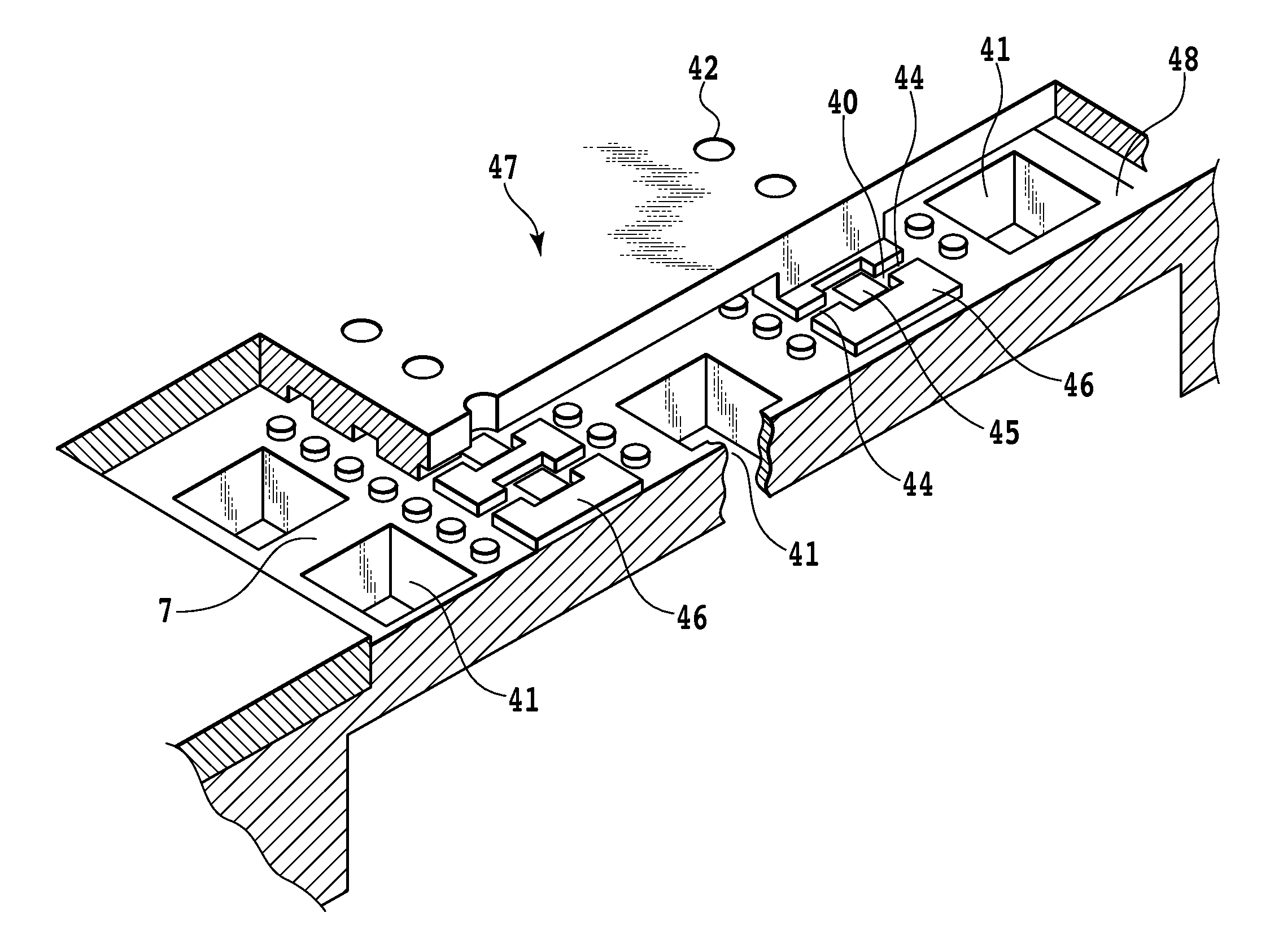
[0063]FIG. 15 is a diagram showing wires connected to print elements 45 in a print head according to the present embodiment. FIG. 15 shows an individual wire provided in the lower wiring layer. In the first embodiment, the individual wire is extended so as to lie under the common wire 78. However, the present embodiment avoids extending the individual wire 83 but uses a wire not connected to any other wire, as a dummy wire 153 provided under the common wire 78. That is, the dummy wire 153 does not contribute to energization of the print element 45. As shown in FIG. 15, in the even-number-th pressure chamber 40 from the end of the print element array, one dummy element 153 is provided under the ...
third embodiment
[0068]A third embodiment of the present invention will be described below with reference to the drawings. The basic configuration of the present embodiment is similar to that of the first embodiment. Thus, only the characteristic arrangements of the present embodiment will be described below.
[0069]FIG. 18 is a sectional view of a portion of a print head according to the present embodiment which corresponds to a pressure chamber. In the present embodiment, the individual wire 83 is provided only on one side, but a member 180 formed of the same material as that of the nozzle material 47 is additionally stuck to the surface of the print element board 48 at the ink channel. Thus, a step is formed so as to make the flow resistance equal between the ink channels arranged on the respective opposite sides of the pressure chamber.
[0070]The actual ejection condition of the print head according to the present embodiment indicates that the Y deviation is reduced compared to that in the comparat...
PUM
 Abstract
Description
Claims
Application Information