Chain tensioner

a chain tensioner and chain technology, applied in the direction of belts/chains/gearrings, mechanical equipment, belts/chains/gearrings, etc., can solve the problems of difficult engine smooth start, reduce the force of the chain tensioner, prevent the chain from overtension, and reduce the plunger inclination

Inactive Publication Date: 2010-05-27
NTN CORP
View PDF14 Cites 21 Cited by
  • Summary
  • Abstract
  • Description
  • Claims
  • Application Information

AI Technical Summary

Benefits of technology

[0022]In the chain tensioner according to this invention, because the damper force can be reduced by adjusting the dimensions of the orifice, it is not necessary to increase the leak gap in order to prevent over-tensioning of the chain. Thus, it is possible to reduce inclination of the plunger relative to the cylinder, thereby reducing wear of the inner periphery of the cylinder due to inclination of the plunger.
[0023]Since the flow rate of hydraulic oil from the oil supply passage into the pressure chamber is restricted by the orifice, even when the engine rpm is high and the vibration of the chain is large, the amount of hydraulic oil flowing into the pressure chamber never increases excessively. This reduces the distance by which the plunger protrudes.

Problems solved by technology

In such a case, if the plunger is markedly pushed in under the tension of the chain, the chain tends to slacken when the engine is restarted, which may make it difficult to smoothly start the engine.

Method used


Image

  • Chain tensioner
  • Chain tensioner
  • Chain tensioner

Examples


Embodiment Construction

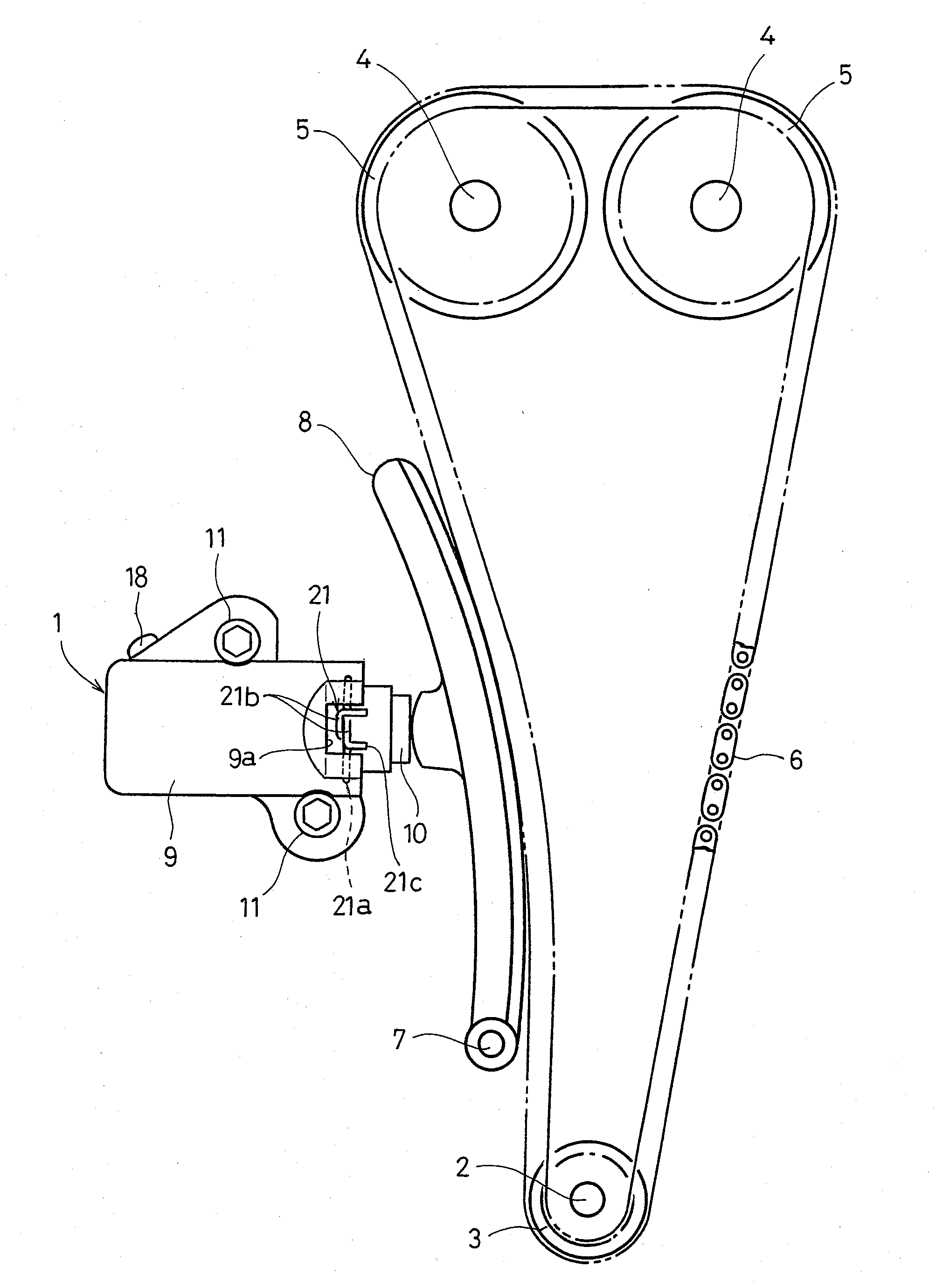
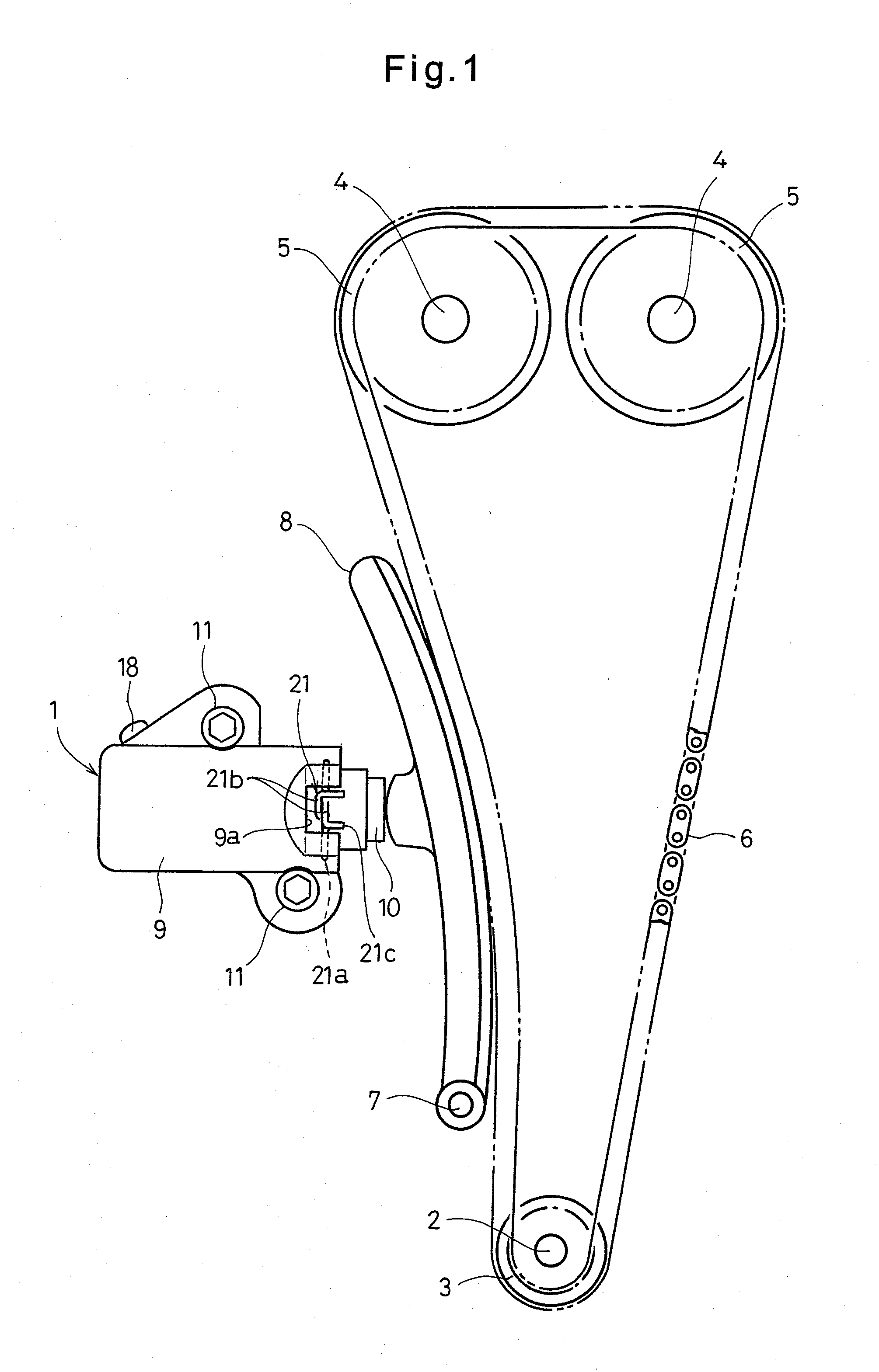
[0029]FIG. 1 shows a chain transmission device including a chain tensioner 1 according to the first embodiment of the present invention. This chain transmission device includes a sprocket 3 fixed to an engine crankshaft 2, sprockets 5 fixed to respective camshafts 4, and a chain 6 coupling the sprockets 3 and 5 together for transmitting the rotation of the crankshaft 2 to the camshafts 4, thereby rotating the camshafts 4 and opening and closing valves (not shown) of combustion chambers.

[0030]A chain guide 8 is pivotally supported on a pivot shaft 7 so as to be kept in contact with the chain 6. The chain 6 is pressed by the chain tensioner 1 through the chain guide 8.

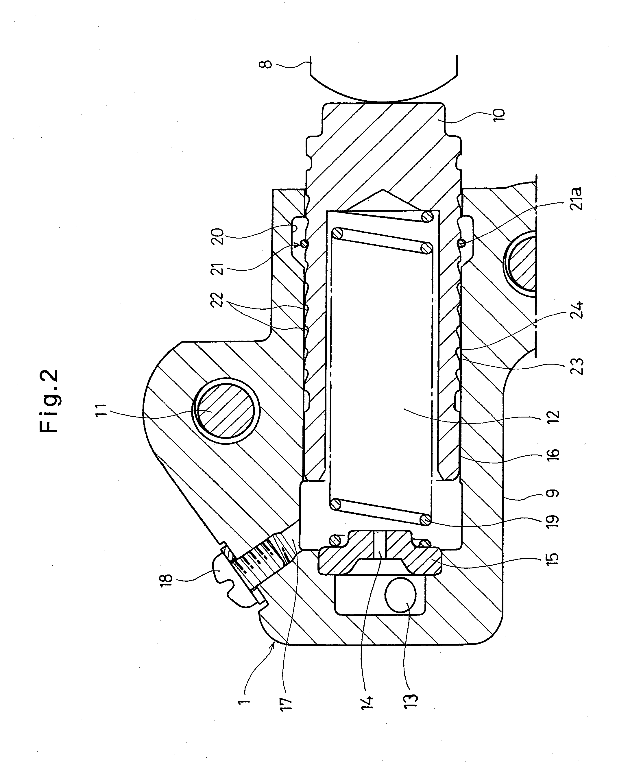
[0031]As shown in FIG. 2, the chain tensioner comprises a cylindrical cylinder 9 having open and closed ends, and a plunger 10 axially slidably inserted in the cylinder 9. The cylinder 9 is fixed to an engine block (not shown) by bolts 11.

[0032]The cylinder 9 is made of aluminum. A surface hardening film is provided on t...


PUM


Abstract

A chain tensioner includes a cylindrical cylinder having a closed end, a plunger slidably mounted in the cylinder, and a return spring biasing the plunger. The cylinder is formed with an oil supply passage through which hydraulic oil is introduced into a pressure chamber defined by the plunger and the cylinder. The oil supply passage has an orifice at its end portion facing the pressure chamber. A leak gap is defined between sliding surfaces of the plunger and the cylinder. A damper force is produced by viscous resistance of hydraulic oil flowing from the pressure chamber through the leak gap, and by viscous resistance of hydraulic oil flowing from the pressure chamber into the oil supply passage through the orifice.

Description

BACKGROUND OF THE INVENTION[0001]This invention relates to a chain tensioner for maintaining the tension of a chain for driving camshafts of an automotive engine.[0002]In a typical automotive engine, the rotation of the crankshaft is transmitted to camshafts through a chain, thereby rotating the camshafts and opening and closing valves of the combustion chambers. In order to keep the tension of the chain within a suitable range, a tension adjusting device is frequently used which includes a chain guide pivotable about a pivot shaft and a chain tensioner for pressing the chain through the chain guide.[0003]A typical chain tensioner used in such a tension adjusting device includes a cylindrical cylinder having open and closed ends, a plunger axially slidably mounted in the cylinder, and a return spring biasing the plunger in a direction to protrude from the cylinder (see JP Patent 3670911 and JP Patent Publication 2001-124159A).[0004]In this chain tensioner, the plunger is adapted to ...

Claims


Application Information

Patent Timeline
Patent Type & Authority Applications(United States)
IPC IPC(8): F16H7/08
CPCF16H7/0836F16H2007/0806F16H2007/0857F16H2007/0853F16H2007/0855F16H2007/0812
Inventor KITANO, SATOSHISATO, SEIJIONIMARU, KOUICHIFURUKAWA, TASUKU
Owner NTN CORP
Why Eureka
Try Eureka