Eureka AIR delivers breakthrough ideas for toughest innovation challenges, trusted by R&D personnel around the world.

Variable-gravity anti-vortex and vapor-ingestion-suppression device

Inactive Publication Date: 2005-01-11
AEROJET ROCKETDYNE OF DE
View PDF11 Cites 21 Cited by
  • Summary
  • Abstract
  • Description
  • Claims
  • Application Information

AI Technical Summary

Benefits of technology

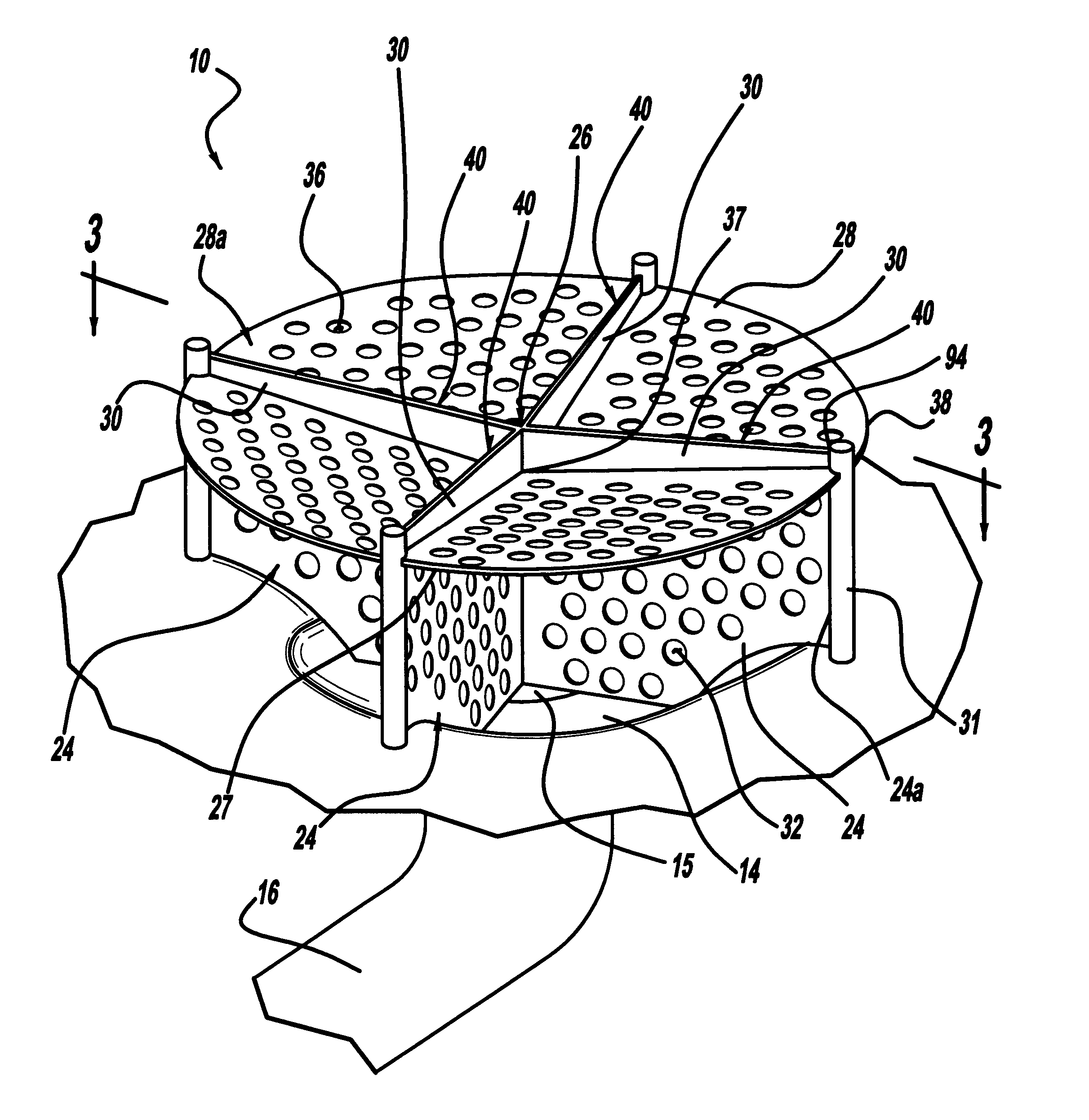
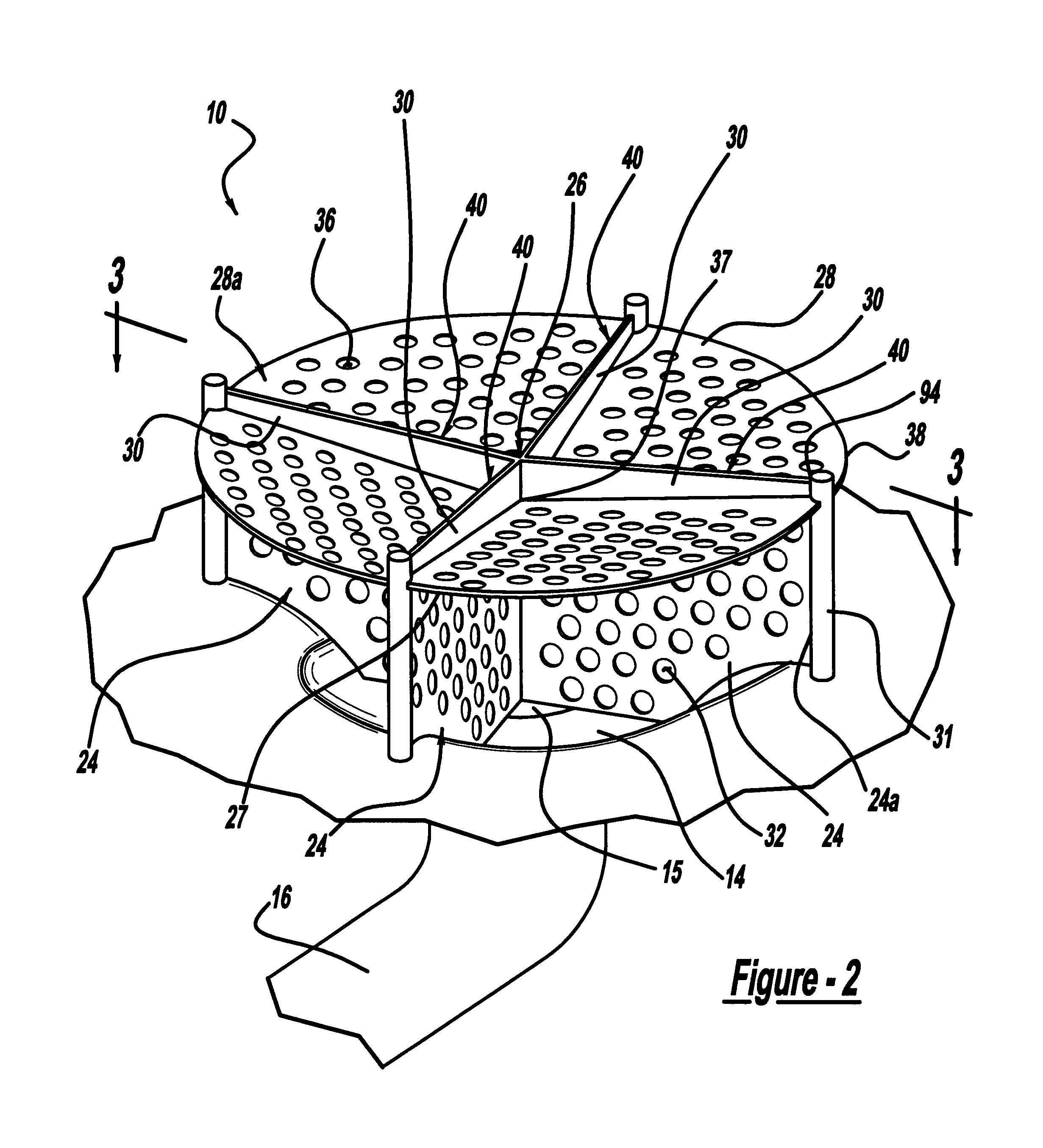
In a first preferred embodiment of the present invention, a storage vessel has an outlet and a liquid propellant management system adjacent the outlet. The liquid propellant management system reduces a dip and a vortex of a liquid, which reduces vapor ingestion into the outlet of the tank in both high gravity environments and low gravity environments. The liquid propellant management system has a first vane with bores, a first end a second end. A plate is also included with bores having a first side and a second side where the first side is operably associated with the first vane. The system also has a second vane operably associated with the second side of the plate. The first vane is adapted to substantially reduce a vortex of a liquid. The plate substantially reduces a dip of a liquid due to frictional energy dissipation, and the second vane provides frictional energy dissipation and substantially wets the plate with a liquid in the tank.
In a second preferred embodiment of the present invention, a liquid propellant management device for use in a liquid storage tank has a first member to suppress the formation of a vortex in a liquid exiting the tank. A plate operably associated with the first member is also included to substantially reduce vapor ingestion into the outlet of the tank. A second member is also included and operably associated with the plate to wet the plate with liquid stored in the tank and provide additional energy dissipation via friction.
In a third preferred embodiment of the present invention, a liquid storage tank is disclosed which has at least an outlet and a liquid management device. The liquid management device has a vortex suppression vane with a plate, to reduce ingestion of vapor, affixed to the top of the vortex suppression vane. Also, a bubble positioning vane is affixed atop the plate. The vortex suppression vane suppresses vortices that attempt to form in liquids as they are exiting the liquid storage tank. The plate reduces the dip due to frictional energy dissipation as the liquid attempts to exit the tank. The bubble positioning vane works to ensure that the plate is wet with liquid at all times during emptying of the liquid storage tank. It also helps to position the bubbles away from the outlet to ensure that ingestion of gas into the outlet is non-existent or minimal.

Problems solved by technology

First, vapor or gas cannot be allowed to enter the engines in any great amount or too early in the ignition process.
If gas is introduced into the engines, it may cause a stall or other malfunctioning of the engine that may increase the possibility of engine failure.
Typically, a portion of liquid propellant still remains in the tank, thereby increasing the vehicle weight and reducing the maximum payload of the vehicle.
Screen systems are made most advantageous only for storage tanks being used in low gravity and are less useful in environments where significant gravity is present.
Additionally, the screen systems typically cannot be used with certain liquid propellants such as hydrogen peroxide due to material incompatibility between H2O2 and typical screen materials.
The vanes used in known vapor ingestion suppression systems, however, are for very low flow rates and cannot provide substantial vapor ingestion suppression at the higher flow rates of many reusable space craft.
Additionally, known systems allow too much fuel to be left in the storage tanks thereby decreasing the efficient use of the fuel stored in the tanks and decreasing the payload for a similarly sized tank and vehicle.
Additionally, the known systems increase the breakdown of certain propellant fluids into gas and non-fuel or inert substances.

Method used


Image

  • Variable-gravity anti-vortex and vapor-ingestion-suppression device
  • Variable-gravity anti-vortex and vapor-ingestion-suppression device
  • Variable-gravity anti-vortex and vapor-ingestion-suppression device

Examples


Embodiment Construction

The following description of the preferred embodiment(s) is merely exemplary in nature and is in no way intended to limit the invention, its application, or uses.

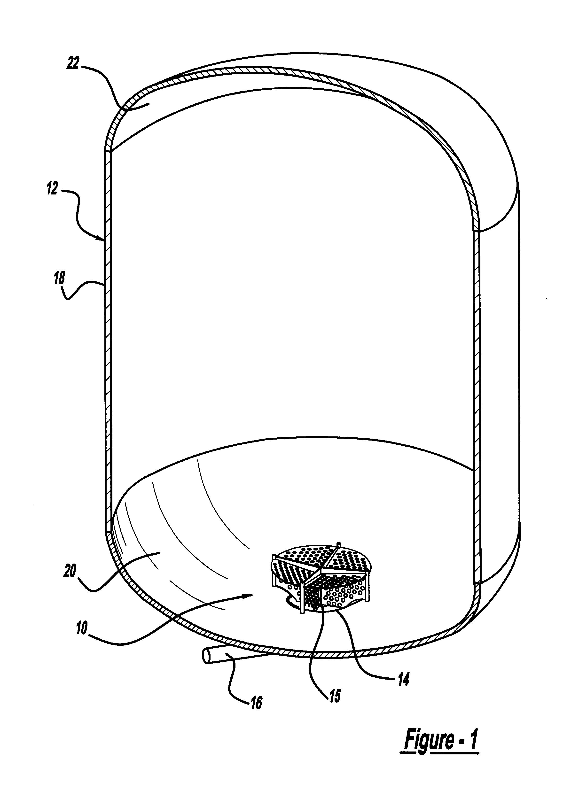
With reference to FIG. 1, a liquid management device or an anti-vortex / vapor-ingestion-suppression device (AVVIS) 10 is shown in accordance with a preferred embodiment of the present invention. The AVVIS 10 operates in variable gravity environments and is affixed within a tank 12 near a sump 14 of tank 12. Sump 14 includes an outlet port 15. Extending externally from tank 12 and connected to outlet port 15 is an outlet line 16. Tank 12 generally has a cylindrical wall 18 extending between a tank bottom 20 and a tank top 22. It will be understood, however, that tank 12 may be any shape suitable for the intended application. Tank 12 is a liquid storage tank where the liquid stored therein exits through sump 14 and outlet port 15 and into outlet line 16. Tank 12 is generally pressurized or has a higher pressure relative to out...


PUM


Abstract

A liquid propellant management device for placement in a liquid storage tank adjacent an outlet of the storage tank to substantially reduce or eliminate the formation of a dip and vortex in the liquid of the tank, as well as prevent vapor ingestion into the outlet, as the liquid drains out through the outlet. The liquid propellant management device has a first member adapted to suppress the formation of a vortex of a liquid exiting the storage tank. A plate is affixed generally perpendicular to the first member, wherein the plate is adapted to suppress vapor ingestion into the outlet by reducing a dip in a surface level of the liquid leaving the tank. A second member is affixed to the second side of the plate. The second member ensures that the plate is wet with liquid and assists in positioning bubbles away from the outlet.

Description

FIELD OF THE INVENTIONThe present invention relates to anti-vortex and vapor-ingestion-suppression devices, and more particularly to an anti-vortex vapor-ingestion-suppression device that works in various gravity environments.BACKGROUND OF THE INVENTIONMany space vehicles, generally use a liquid propellant which is stored in storage tanks and fed into engines during take off and flight in space. The liquid must be moved from the storage tanks to the engine in an efficient manner. First, vapor or gas cannot be allowed to enter the engines in any great amount or too early in the ignition process. If gas is introduced into the engines, it may cause a stall or other malfunctioning of the engine that may increase the possibility of engine failure. It is generally known in the art to provide a device that is be placed in the propellant storage tanks which will reduce the acquisition of gas into the engine. Second, it is desirable to empty the storage tanks as completely as possible during...

Claims


Application Information

Patent Timeline
IPC IPC(8): B64G1/22B64G1/40F02K9/00F02K9/60
CPCF02K9/60B64G1/402Y10T137/85938Y10T137/86348Y10T137/86212B64G1/4021
Inventor GRAYSON, GARY D.
Owner AEROJET ROCKETDYNE OF DE
Why Eureka
Eureka Blog
Learn More