Air intake system

a technology of air intake system and air intake pipe, which is applied in the direction of machine/engine, combustion-air/fuel-air treatment, and separation processes, to achieve the effects of facilitating water drainage, reducing water progress, and preventing water entry

Active Publication Date: 2006-07-04
FORD MOTOR CO
View PDF13 Cites 21 Cited by
  • Summary
  • Abstract
  • Description
  • Claims
  • Application Information

AI Technical Summary

Benefits of technology

[0006]The present invention is generally directed to a novel air intake system which is suitable for at least substantially reducing the intake of water with ambient air into an air compressor or other operational component of a fuel cell or internal combustion engine. The air intake system includes a combination of multiple devices which are situated in an elongated air flow conduit to at least substantially reduce the progress of water into the operational component or components of the vehicle. The devices include an air inlet arm which is fitted with angled grill louvers to hinder the entry of water into the air flow conduit, a splash shield provided in the air inlet arm to divert from the air flow conduit water that passes beyond the grill louvers, backflow surfaces provided in the air inlet arm to facilitate the drainage of water from the air inlet arm, a vertical “head height” between the air inlet arm and a transverse segment of the air flow conduit to prevent or reduce further flow of water through the air flow conduit by gravity, a gullet chamber situated beneath the air intake arm for collecting the diverted water, and a standard air filter which absorbs any water which reaches it and is eventually dried through normal operation.

Problems solved by technology

The ambient air is fed to a positive displacement air compressor, which is susceptible to liquid water that may be inadvertently drawn in with the ambient air.

Method used


Image

  • Air intake system
  • Air intake system
  • Air intake system

Examples


Embodiment Construction

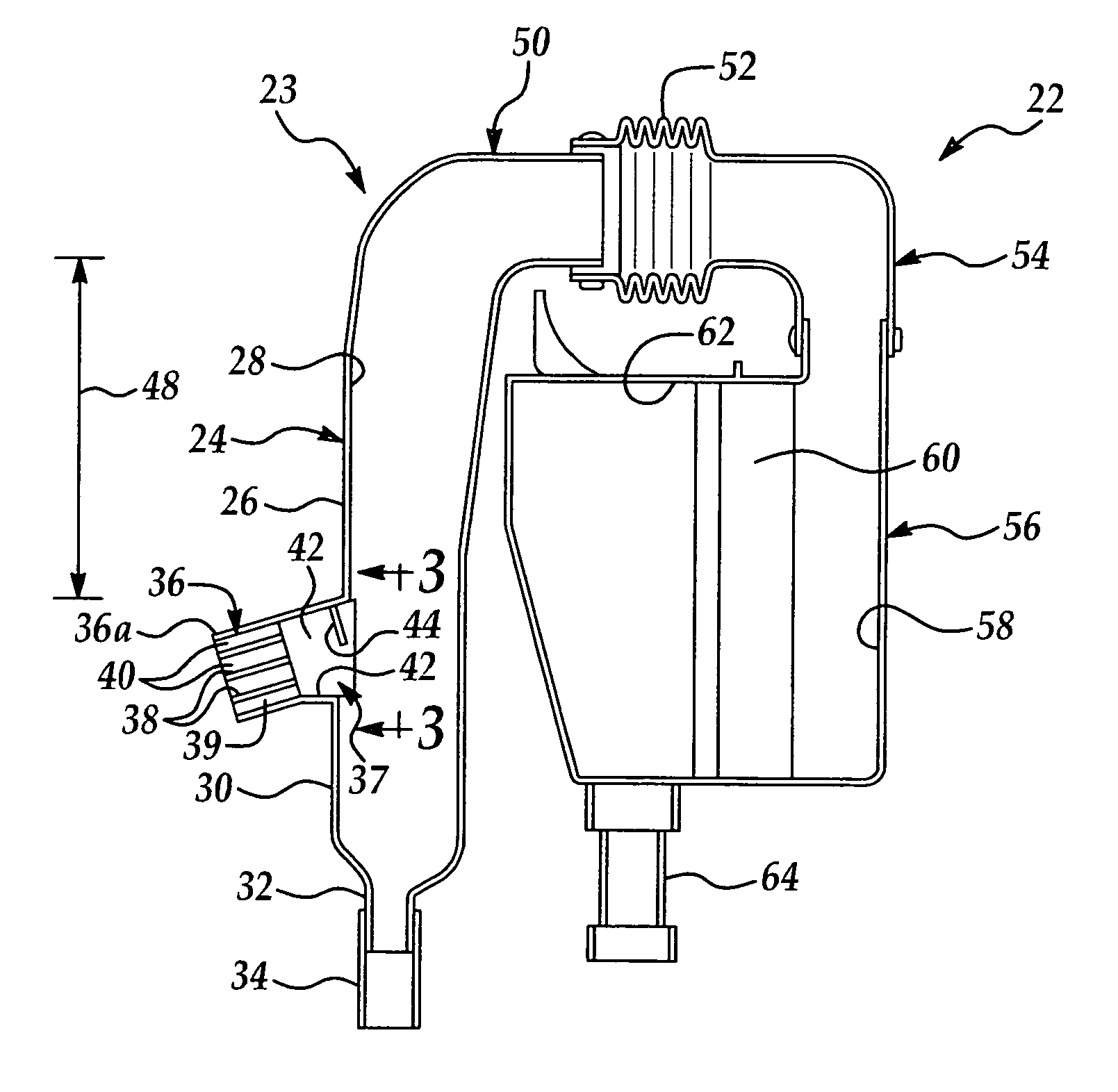
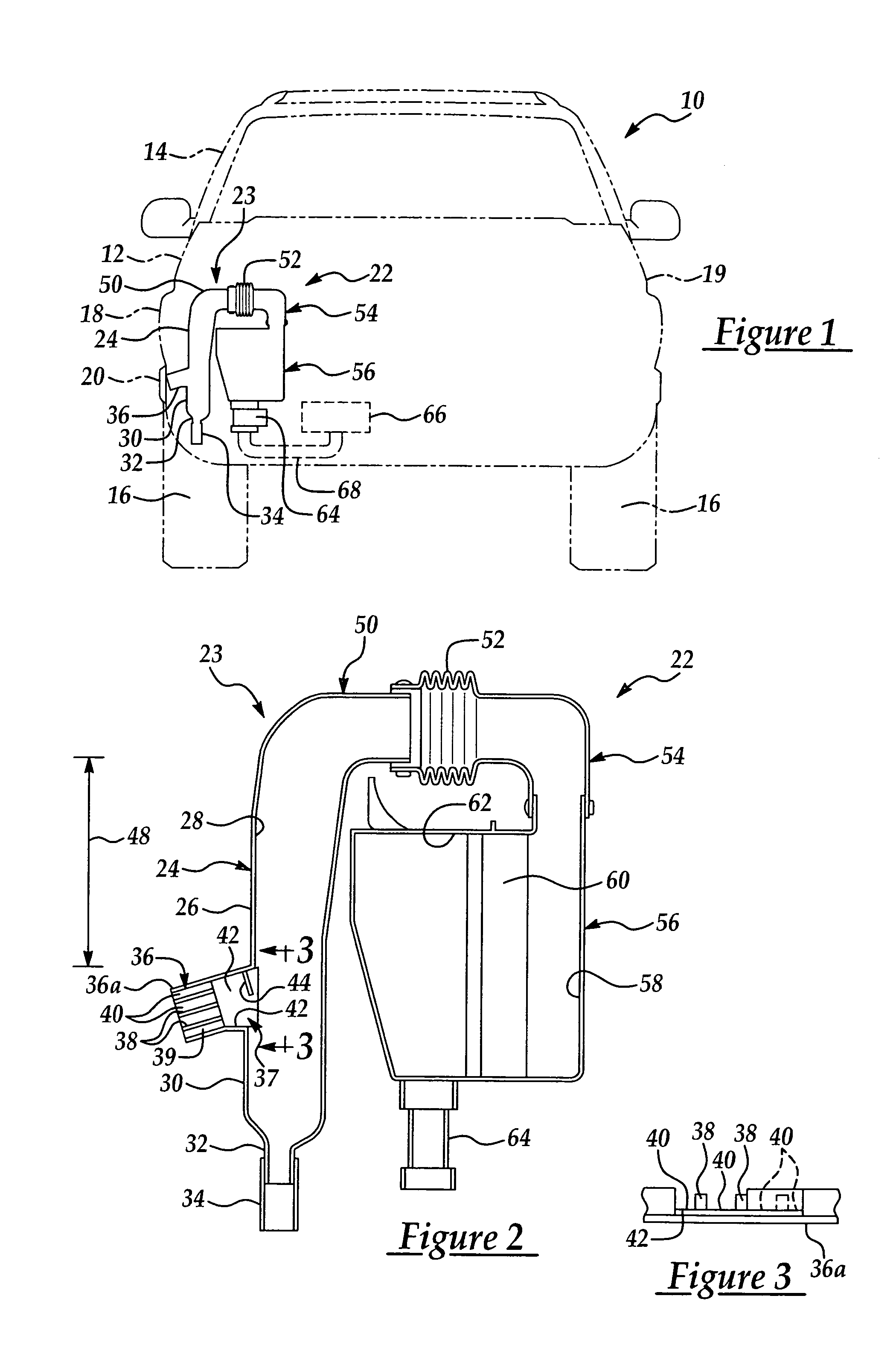
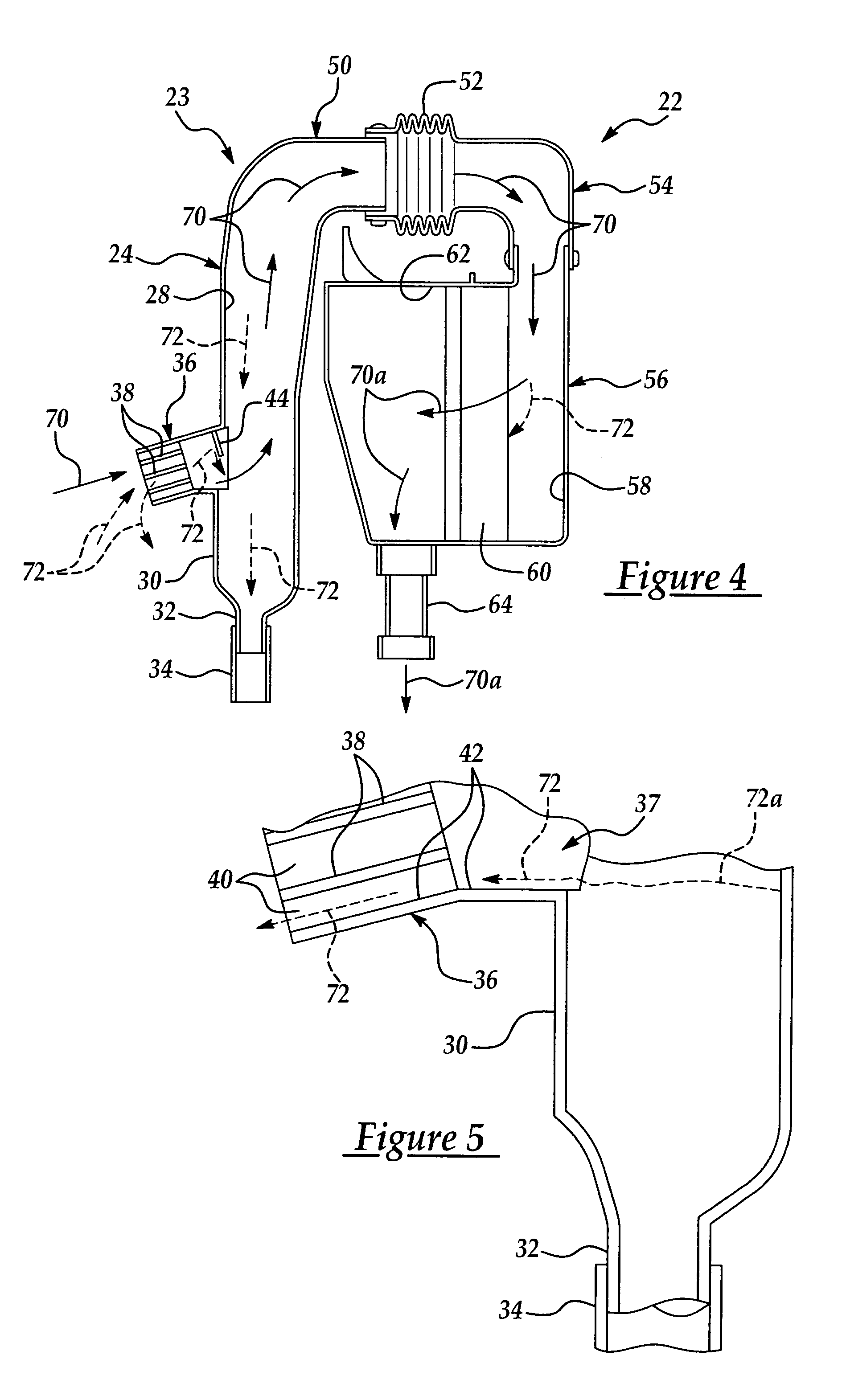
[0013]The present invention contemplates a novel air intake system which is particularly adapted for use in a fuel cell electric vehicle to at least minimize the ingress of water with ambient air into a positive displacement air compressor which delivers compressed ambient air as an oxygen source to an electricity-generating fuel cell or cells. However, the air intake system of the present invention is equally adaptable to internal combustion engines and other systems in which air is to be delivered to a destination in a substantially water-free state.

[0014]Referring initially to FIG. 1, an illustrative fuel cell electric vehicle 10 is indicated in phantom in rear view. The fuel cell electric vehicle 10 typically includes a chassis 12 and a cabin 14. The vehicle 10 typically includes four wheels, including a pair of spaced-apart rear wheels 16. The chassis 12 typically includes a rear left quarter panel 18, a rear right quarter panel 19, a front left quarter panel (not shown) and a ...


PUM

PropertyMeasurementUnit
gap distanceaaaaaaaaaa
angleaaaaaaaaaa
electrical poweraaaaaaaaaa

Abstract

A novel air intake system which is suitable for at least substantially reducing the inadvertent intake of water with ambient air into an air compressor or other operational component of a fuel cell or internal combustion engine is disclosed. The air intake system typically includes an elongated air flow conduit having a downwardly-angled air inlet arm that is typically fitted with multiple louver elements and a splash shield to deflect entering water downwardly into a drain or gullet chamber. The air intake system typically further includes a mechanism for gravity-mediated draining of water from the air flow conduit to prevent entering water from being drawn into the air compressor or other component.

Description

FIELD OF THE INVENTION[0001]The present invention relates generally to air intake systems which conduct air from outside a vehicle to an engine or other operational components of the vehicle. More particularly, the present invention relates to a novel side-air intake system which includes multiple components that are designed to prevent or minimize entry of water into an air compressor of a fuel cell electric vehicle or into an internal combustion engine of a vehicle as air is drawn from outside the vehicle into the air compressor or engine.BACKGROUND OF THE INVENTION[0002]Fuel cell technology has been identified as a potential alternative for the traditional internal-combustion engine conventionally used to power automobiles. It has been found that power cell plants are capable of achieving efficiencies as high as 55%, as compared to maximum efficiency of about 30% for internal combustion engines. Furthermore, fuel cell power plants produce zero tailpipe emissions and produce only ...

Claims


Application Information

Patent Timeline
Patent Type & Authority Patents(United States)
IPC IPC(8): F02M35/10B01D45/00B60K13/02F02M35/00F02M35/02F02M35/022F02M35/16H01M8/04
CPCF02M35/022F02M35/10013F02M35/10144F02M35/161F02M35/10262Y02T10/146Y02E60/50Y02T10/12B01D45/00F02M35/16H01M8/04
Inventor CUSUMANO, THOMASSMITH, CRAIG
Owner FORD MOTOR CO
Why Eureka
Try Eureka