Method and apparatus to reduce stalk shear

a technology of stalk shear and apparatus, applied in the field of corn harvesting machinery, can solve the problems of reducing the efficiency of the stalk, affecting the harvesting equipment, and affecting the harvesting efficiency of corn, so as to reduce the intake of trash and increase the harvesting ground speed

Inactive Publication Date: 2005-06-09
CALMER MARION
View PDF5 Cites 20 Cited by
  • Summary
  • Abstract
  • Description
  • Claims
  • Application Information

AI Technical Summary

Benefits of technology

[0017] It is an objective to teach a method and apparatus that may allow existing corn head row units with dependent drive systems to reduce the intake of trash or material other than ears (MOTE) and increase harvester ground speed.

Problems solved by technology

Through research, operations, and testing, applicant has found that a major evolving problem in harvesting today's corn hybrids is a large build up of plant material (MOTE plus ears) in front of the cross auger during operation of the corn head.
The accumulation of MOTE reduces the efficiency of the corn head.
The appearance of this fluff or trash may be severe enough to require harvesting equipment to shut down.
When harvesting down corn it was also noticed that root balls were unnecessarily being pulled out of the ground and dragged into the corn head due to excessive gathering chain speed.
There are numerous disadvantages and weaknesses in the teachings found in Chamberlain.
This increase in equipment increases the weight of the corn head and the power required to drive the head, increasing both the cost of manufacture and operation.
Additionally, Chamberlain does not teach a method to convert an existing corn head having a dependent drive system.
The problem at its most basic is that the stalk roll flutes and the gathering chain paddles are applying energy to the stalk in different directions producing a shearing effect.
When the corn stalk reaches the end of the stalk rolls and stops moving horizontally, the movement of the corn stalk becomes restricted.
This would indicate there is significant pressure and wear at this point due to stalks separating against the stripper plate.
The weakness in this node accentuates the tendency of the prior art to separate the stalk from itself when the stalk is subjected to shear.

Method used


Image

  • Method and apparatus to reduce stalk shear
  • Method and apparatus to reduce stalk shear
  • Method and apparatus to reduce stalk shear

Examples


Embodiment Construction

[0045]

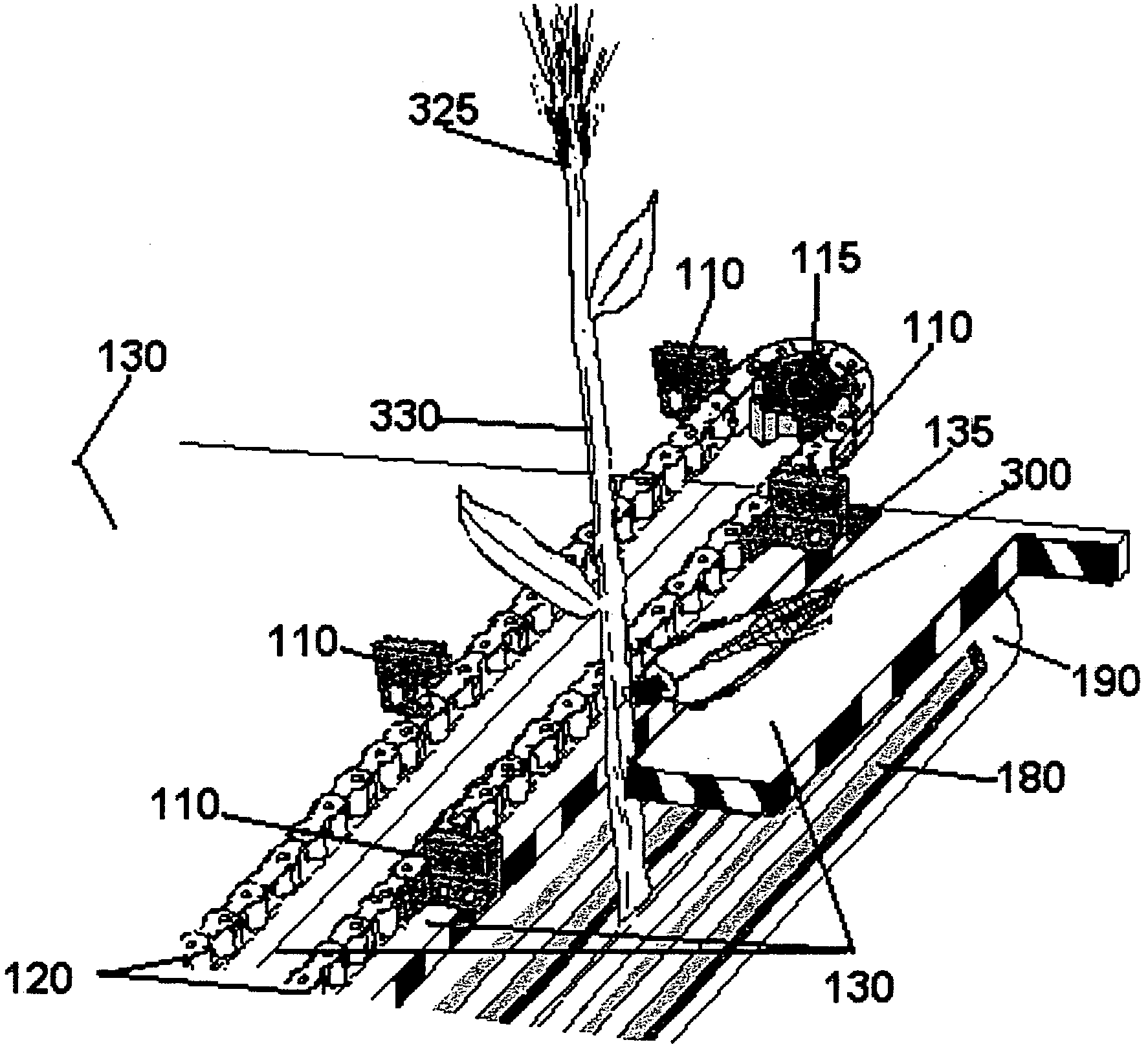
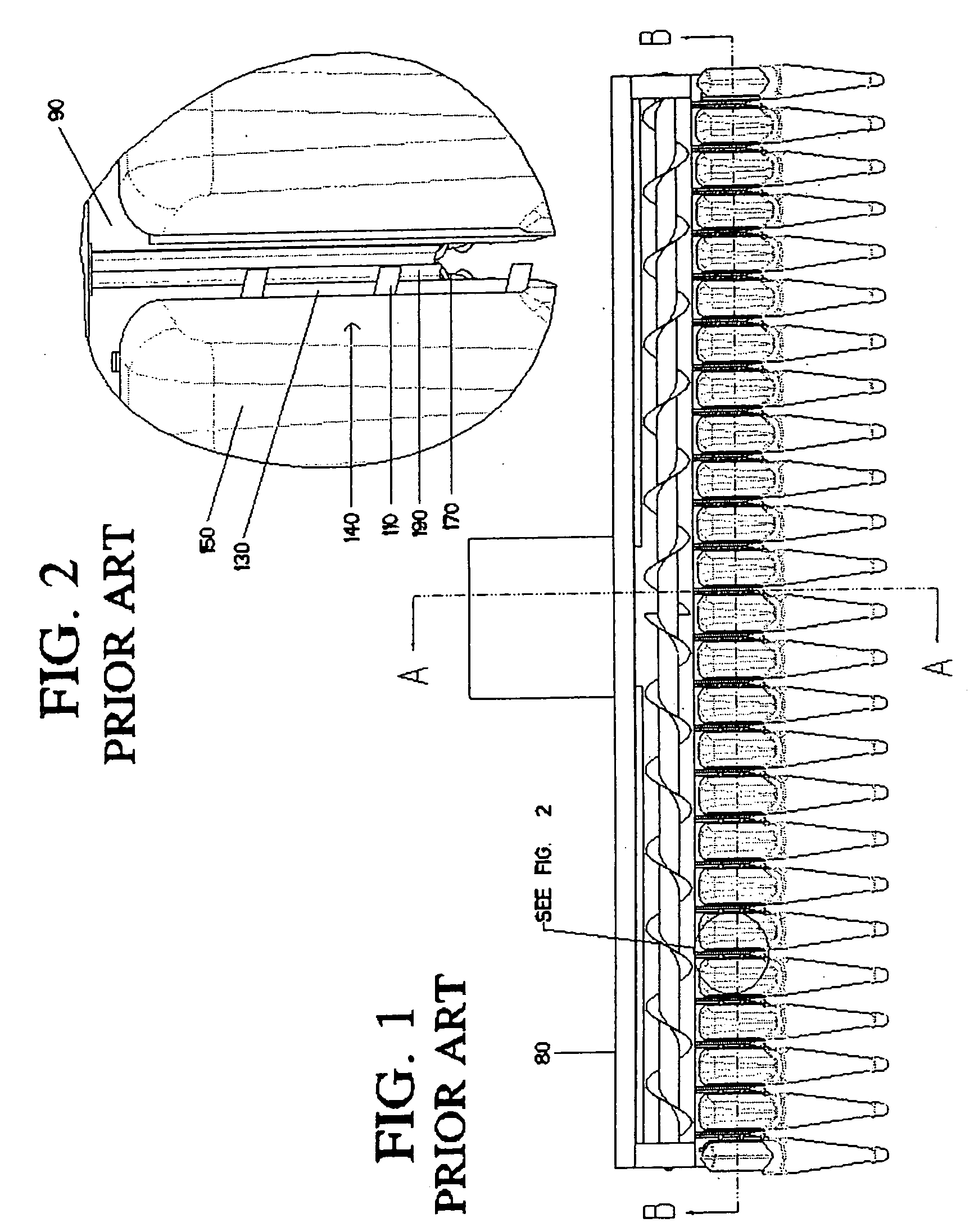
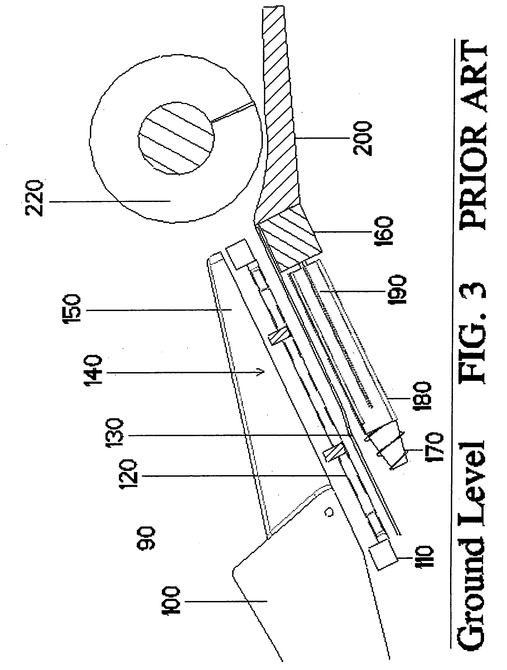
Listing of the ElementsDescriptionNumberCorn head80Row unit90Row unit dividers100Gathering chain paddles1108 tooth gathering chain drive sprocket (Prior Art)1125 tooth gathering chain drive sprocket115Gathering chain120Stripper plates130Row unit shear point135Ear Separation Chamber140Row unit covers150Gearbox160Transport vanes170Stalk Roll flutes180Stalk rolls190Cross Auger Trough200Cross Auger220Corn plant ear300Upper Portion of Corn Plant Stalk325Lower Portion of Corn Plant Stalk330

[0046] The general operation of corn heads incorporating this invention in FIGS. 1 through 9 are similar to that of the operation of corn heads of the prior art as illustrated in FIGS. 1, 2 and 3. As shown in FIG. 1, corn heads are provided with several row crop dividers 100 for retrieving, lifting, and directing the rows of corn stalks toward there respective ear separation chambers 140. In FIGS. 1 and 3 the corn stalks are lifted and guided toward the row unit 90 by row unit dividers 100. Row un...


PUM


Abstract

The invention provides four (4) methods to reduce stalk shear in a corn head row unit that utilizes a non-variable or dependent drive system. The four methods described include altering the gearbox ratio, increasing the lengths of the fluted portion of the stalk roll, increasing stalk roll diameter or reducing the size of the gathering chain drive sprocket. The invention allows for a more balanced application of multi directional energy to be applied to the corn plant. The resultant effect is to reduce stalk shear which reduces trash intake to the harvester. This novel idea provides the first means and method to which genetically improved taller and healthier corn plants can be harvested with minimal amounts of material other than ears ultimately being transferred to the threshing unit.

Description

STATEMENT REGARDING FEDERALLY SPONSORED RESEARCH OF DEVELOPMENT [0001] No federal funds were used to develop or create the invention disclosed and described in the patent application. BACKGROUND OF THE INVENTION [0002] This invention relates to corn harvesting machinery and more particularly the corn row unit of the corn head commonly used with modern self-propelled combines. Corn heads include individual row units normally designed for harvesting a single row of crop material. To accommodate various spacings between rows of crops, these row units are usually adjustably attached to a horizontally disposed frame member. The modern trend in corn headers appears to be one of placing the row units at a low profile to the ground, closer together and providing for increasingly larger throughputs. [0003] Each row unit contains a row crop divider, a row unit hood, gathering / conveying chain(s), two stripper plates, two stalk rolls, a row unit frame, and a gearbox. The gearbox powers the row ...

Claims


Application Information

Patent Timeline
Patent Type & Authority Applications(United States)
IPC IPC(8): A01D45/02
CPCA01D45/021A01D45/023
Inventor CALMER, MARION
Owner CALMER MARION
Why Eureka
Try Eureka