Cutting plate for a drill bit

a technology for cutting plates and drill bits, which is applied in the direction of tool workpiece connection, twist drills, manufacturing tools, etc., can solve the problem of reducing the likelihood of auxiliary cutting plates being removed from drill bits during use, and achieve the effect of maintaining the cutting performance of auxiliary cutting plates

Active Publication Date: 2005-06-16
BLACK & DECKER INC
View PDF11 Cites 20 Cited by
  • Summary
  • Abstract
  • Description
  • Claims
  • Application Information

AI Technical Summary

Benefits of technology

[0012] The present invention overcomes, or at least mitigates, the removal problem of the auxi

Problems solved by technology

This reduces the likelihood of the auxiliary cuttin

Method used


Image

  • Cutting plate for a drill bit
  • Cutting plate for a drill bit
  • Cutting plate for a drill bit

Examples


Embodiment Construction

[0031] The following description of the preferred embodiment(s) is merely exemplary in nature and is in no way intended to limit the invention, its application, or uses.

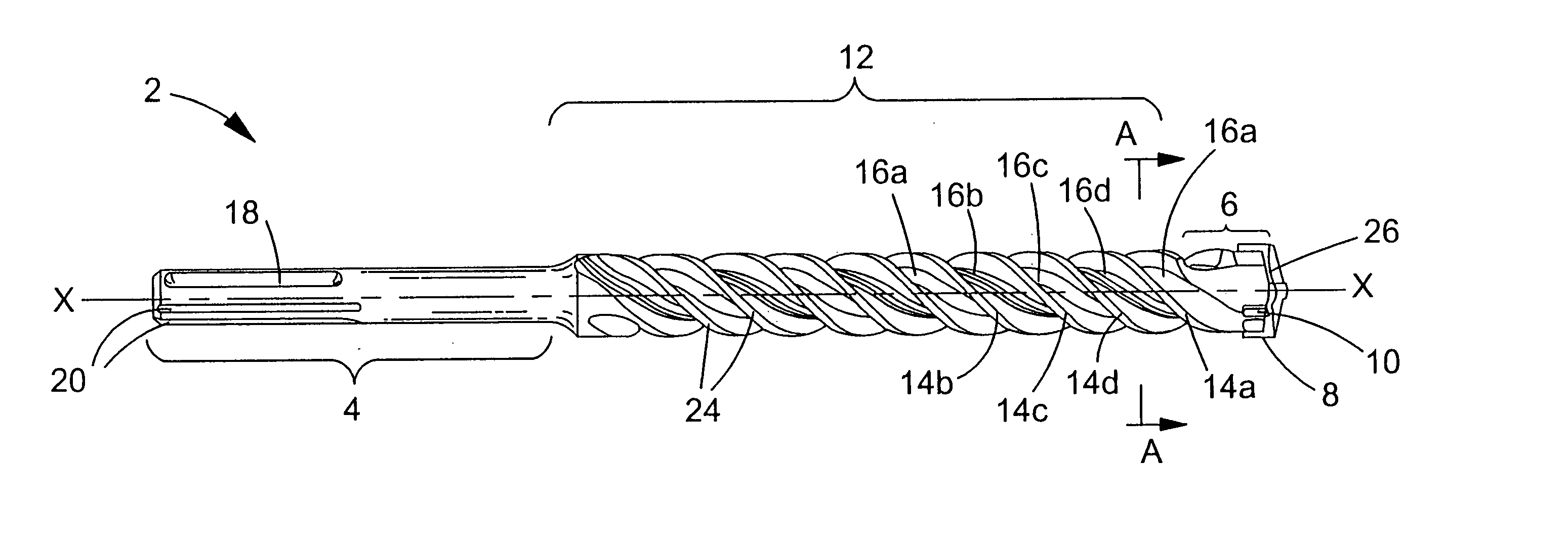
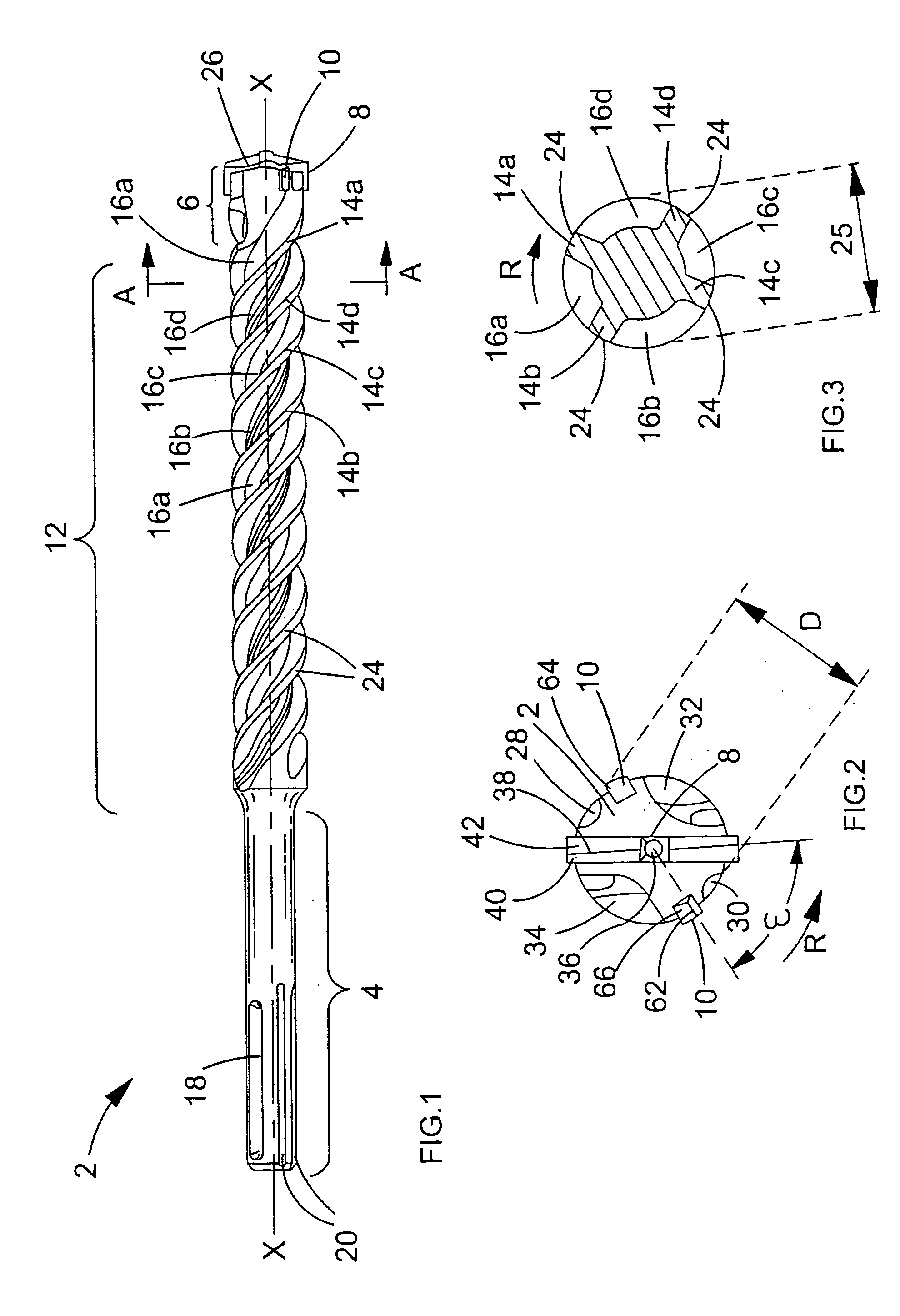
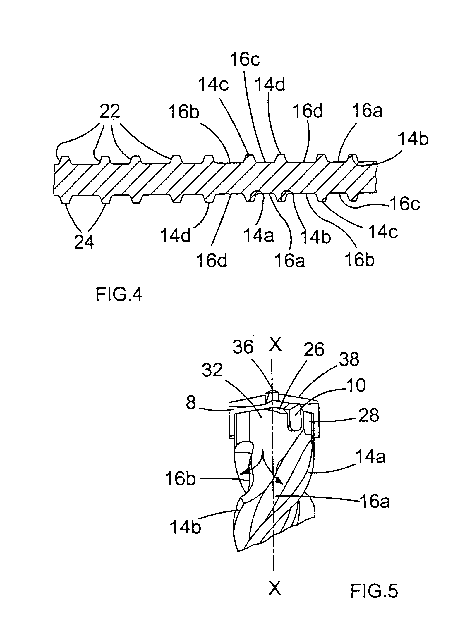
[0032] FIGS. 1 to 5 show a design of a drill bit 2 having a diameter of between 16 mm and 52 mm. The drill bit has a longitudinal axis X-X. The drill bit 2 has a clamping shank 4 at its rear end that can be releasably fitted within a tool holder of a rotary hammer. The drill bit 2 has a drilling head 6 at its forward end within which are mounted a carbide primary cutting plate 8 and a pair of auxiliary carbide cutting plates 10. The tool has an intermediate helical conveying portion 12 extending between the shank 4 and the drilling head 6 around which extend four helical webs 14a-14d and corresponding helical flutes 16a-16d.

[0033] The shank 4 of the drill bit shown in FIG. 1 is configured as a SDS-Max clamping shank 4, as is well known in the art. The shank 4 comprises a pair of opposing axially closed grooves 18. ...


PUM

PropertyMeasurementUnit
Angleaaaaaaaaaa

Abstract

An auxiliary cutting plate (10) for a multi-cutting plate drill bit (2) has a body (44) for fixing into a slot in the drill bit (2) and a profiled tip (46). The body (44) has a central longitudinal axis and the profiled tip (46) protrudes from one end of the body (44). The profiled tip (46) has a cutting edge (62) defined by a transition between a rake face (64) and a relief face (66). The rake face (64) and the relief face (66) each slope axially rearward from opposite sides of the cutting edge (62). The angle of inclination 0 of at least a portion of the rake face (64), measured from a plane perpendicular to the longitudinal axis, decreases with increasing distance from the cutting edge (62).

Description

CROSS-REFERENCE TO RELATED APPLICATIONS [0001] This application claims priority to United Kingdom Patent Application No. GB 0318851.3 filed Aug. 12, 2003, which application is herein expressly incorporated by reference. FIELD OF THE INVENTION [0002] The present invention relates to a cutting plate for a drill bit and, more particularly, to an auxiliary cutting plate for a multi-cutting plate drill bit. BACKGROUND OF THE INVENTION [0003] In existing designs, cutting plates have a generally rectangular body with a profiled tip for cutting a workpiece, for example, masonry. The body is welded, brazed or fixed by other mechanical means to a drilling head located at one end of a shaft of a drill bit having a longitudinal axis. The profiled tip of the cutting plate protrudes axially from the drilling head. Located at the other end of the shaft is a shank to releasably connect to a tool holder or a drill or the like, for example, a rotary drill, a rotary percussion drill or a rotary hammer...

Claims


Application Information

Patent Timeline
IPC IPC(8): B23B27/02B23B51/00B23B51/02B28D1/14E21B10/00E21B10/44
CPCB23B51/02B23B2226/18B23B2226/75B23B2240/08B23B2251/50B23B2251/14B23B2251/204B23B2251/406B23B2251/04
Inventor MEIERHOFER, MARKUSEGGERS, RAINER
Owner BLACK & DECKER INC
Why Eureka
Try Eureka