Cutting apparatus and cutting method

a cutting apparatus and cutting technology, applied in the direction of metal working apparatus, electric devices, fine working devices, etc., can solve the problems of clogging the cutting blade, and lowering the cutting performance of the cutting blade, so as to prevent the workpiece and the cutting blade from being broken, lowering the cutting performance, and preventing the effect of cutting performan

Inactive Publication Date: 2016-10-27
DISCO CORP
View PDF7 Cites 18 Cited by
  • Summary
  • Abstract
  • Description
  • Claims
  • Application Information

AI Technical Summary

Benefits of technology

[0011]In the cutting apparatus and the cutting method of the present invention, foreign matter (adhered matter) adhered to the cutting blade is removed by the cleaning fluid jetted from the cleaning fluid jetting means. This makes it possible to prevent cutting performance from being lowered due, for example, to adhesion of debris (cuttings) to the cutting blade. Therefore, according to the present invention, it is possible to prevent the workpiece and the cutting blade from being broken due to a lowering in cutting performance.

Problems solved by technology

When the cutting blade is made to cut into the dicing tape, therefore, the debris (cuttings) generated at the dicing tape are likely to stick to the cutting blade, resulting in clogging.
Similarly, when a workpiece formed of a metal, resin or the like having high viscosity or a workpiece having a highly viscous material disposed at predetermined processing lines is cut by use of the aforementioned cutting blade, the debris (cuttings) generated from the workpiece are likely to stick to the cutting blade, thereby clogging the cutting blade.
Such a clogging of the cutting blade lowers the cutting performance of the cutting blade.
A lowering in the cutting performance of the cutting blade, in turn, is likely to cause the generation of defects such as chippings and burring in the workpiece.
In addition, the cutting blade in such a situation is liable to meander under the load during cutting, and the possibility of breaking of the cutting blade itself is raised.

Method used


Image

  • Cutting apparatus and cutting method
  • Cutting apparatus and cutting method
  • Cutting apparatus and cutting method

Examples


Embodiment Construction

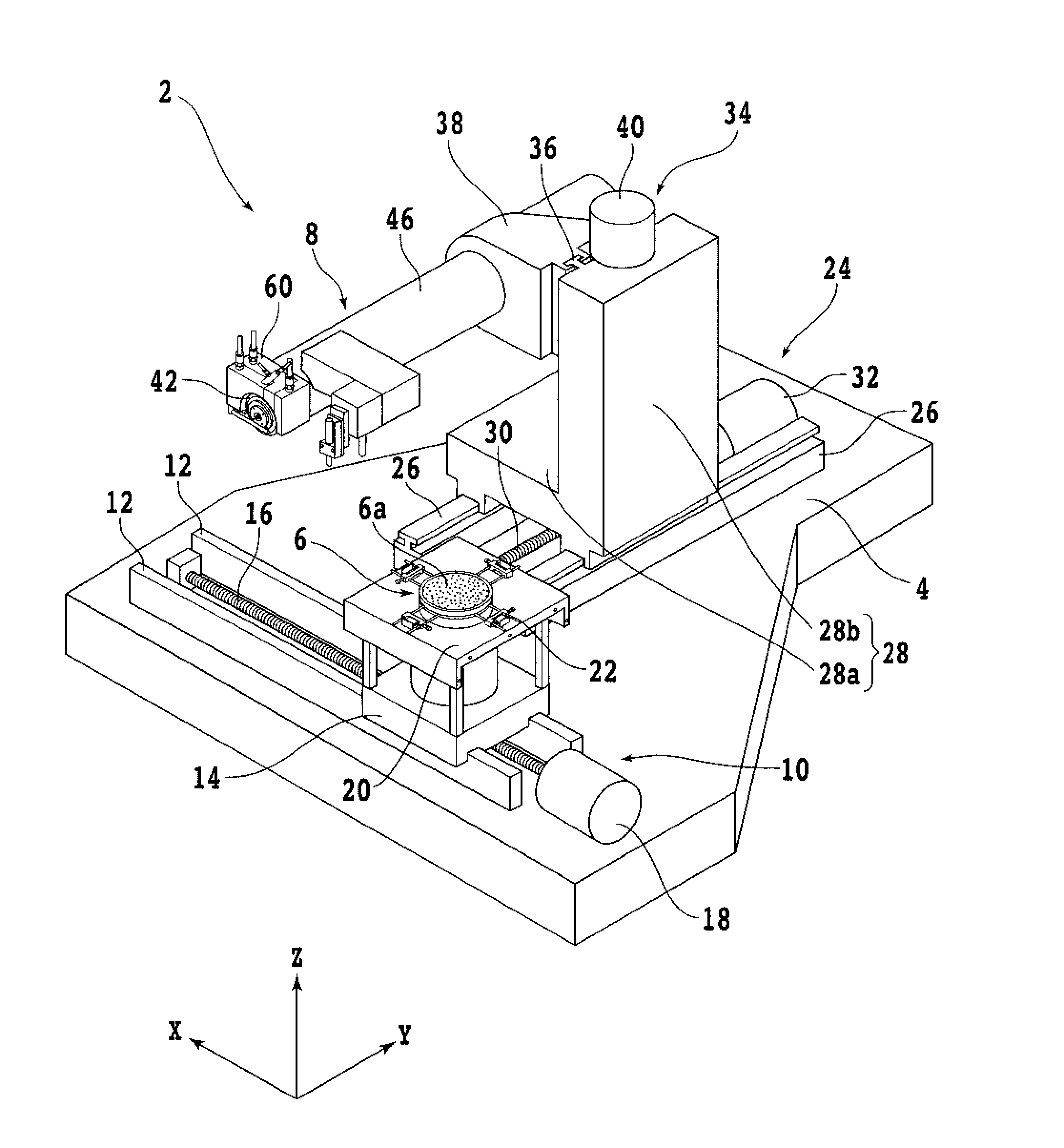
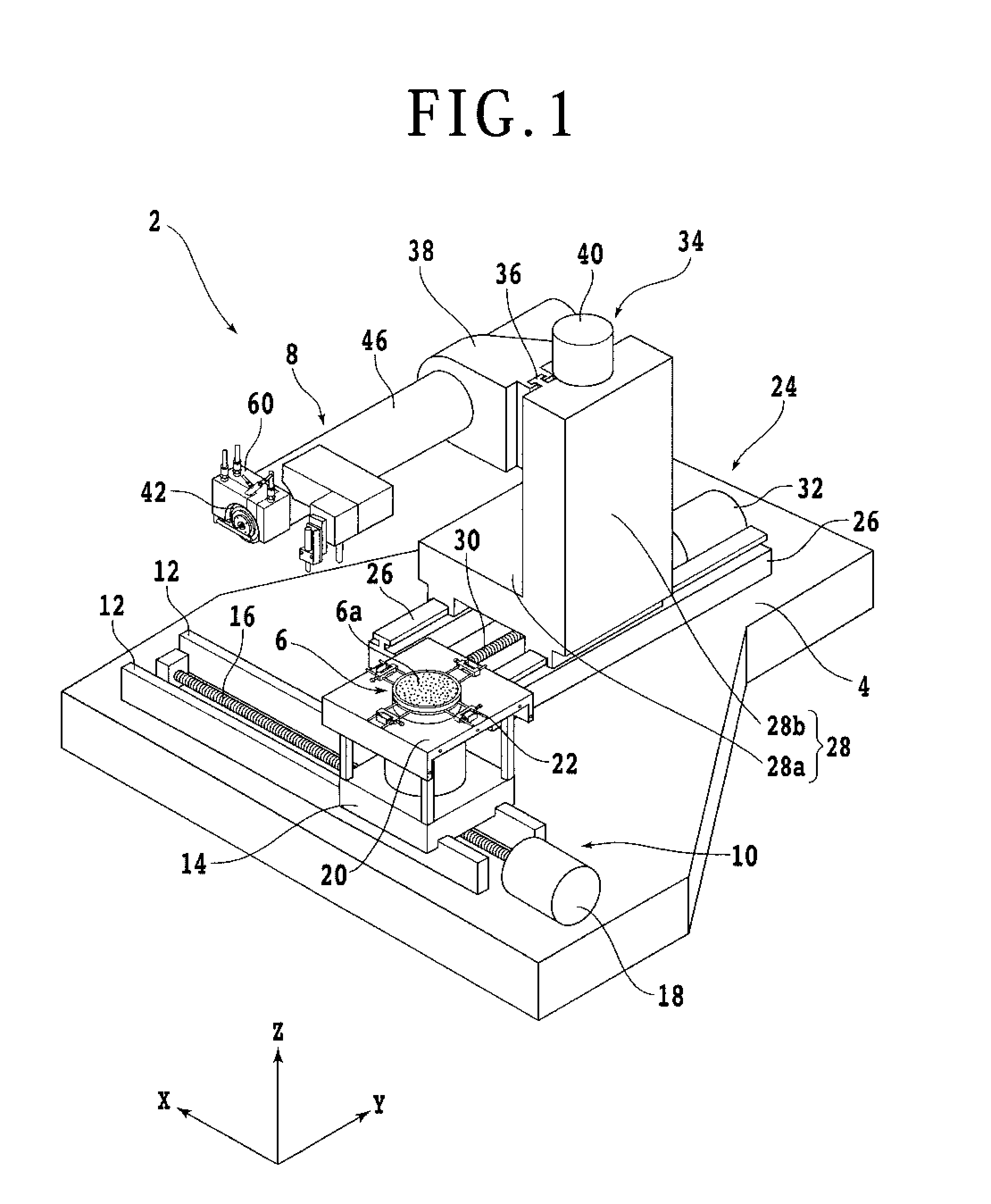
[0020]An embodiment of the present invention will be described below, referring to the attached drawings. FIG. 1 is a perspective view showing schematically a configuration example of a cutting apparatus according to an embodiment of the present invention. As shown in FIG. 1, the cutting apparatus 2 has a base 4 for supporting each component. On the upper side of the base 4 is provided a chuck table (holding means) 6 for holding a workpiece 11 (see FIG. 4A) such as a semiconductor wafer and a glass substrate. Over the chuck table 6 is disposed a blade unit (cutting means) 8 for cutting the workpiece 11.

[0021]Under the chuck table 6 is provided an X-axis moving mechanism (feeding mechanism) 10 for moving the chuck table 6 in a feeding direction (X-axis direction). The X-axis moving mechanism 10 includes a pair of X-axis guide rails 12 fixed to an upper surface of the base 4 and extending in parallel to the X-axis direction. On the X-axis guide rails 12, an X-axis moving table 14 is d...


PUM

PropertyMeasurementUnit
pressureaaaaaaaaaa
pressureaaaaaaaaaa
abrasiveaaaaaaaaaa

Abstract

A cutting apparatus for cutting a workpiece includes: a holding unit for holding the workpiece; a cutting unit including a cutting blade for cutting the workpiece held by the holding unit, and a spindle for rotating the cutting blade; a cutting water supplying unit for supplying cutting water to the cutting blade; and a cleaning fluid jetting unit for jetting to the cutting blade a cleaning fluid for removal of matter adhered to the cutting blade.

Description

BACKGROUND OF THE INVENTION[0001]1. Field of the Invention[0002]The present invention relates to a cutting apparatus and a cutting method for cutting a workpiece such as a semiconductor wafer.[0003]2. Description of the Related Art[0004]A workpiece such as a semiconductor wafer and a glass substrate is cut by a cutting apparatus having a rotating annular cutting blade, for example, and is thereby divided into a plurality of chips (see, for example, Japanese Patent Laid-open No. 2007-59432). Prior to the cutting of the workpiece, a dicing tape is attached to the back side of the workpiece, and an annular frame surrounding the workpiece is fixed to a peripheral portion of the dicing tape. This makes it possible to prevent scattering of the chips after the cutting and thereby to maintain handleability of the chips. The aforementioned cutting blade is formed by binding abrasive grains of diamond, CBN (cubic boron nitride) or the like with a binder such as a metal or resin. The cutting b...

Claims


Application Information

Patent Timeline
Patent Type & Authority Applications(United States)
IPC IPC(8): B26D7/08H01L21/67B28D5/02H01L21/78B26D7/01B26D7/18
CPCB26D7/088B26D7/01H01L21/67092B28D5/022H01L21/78B26D7/18B26F1/3826
Inventor ITATANI, YUYAISHIAI, YOSHIKI
Owner DISCO CORP
Why Eureka
Try Eureka