Cutting insert having cylindrically shaped side surface portions

a cutting insert and side surface technology, applied in the field of double-sided, can solve the problems of constant setting angle of the minor cutting edge of each cooperating pair, affecting the face of the workpiece being milled, etc., and achieve the effect of reducing cutting performance, reducing positioning deviation, and reducing the smoothness of the workpiece fa

Active Publication Date: 2007-06-19
ISCAR LTD
View PDF9 Cites 58 Cited by
  • Summary
  • Abstract
  • Description
  • Claims
  • Application Information

AI Technical Summary

Benefits of technology

[0026]Because the entire length of each minor edge constitutes a wiper edge, positional deviation of the cutting insert in the insert pocket may not lead to reduced cutting performances, so that the wiper edge may be able to continue machining the work-piece face, substantially without compromising the smoothness of the work-piece face and to the quality of the finished product;
[0027]Peripheral surfaces of cutting inserts are often ground to reduce positioning deviation and to achieve a high quality finished product; however, the cutting insert of the present invention is capable of reducing the effects of positional deviation without necessitating grinding of the peripheral side surface.

Problems solved by technology

A drawback of these known inserts is that the minor cutting edge of each cooperating pair has a constant setting angle during the machining of the work-piece.
Positioning deviation of the cutting insert relative to a cutter body of a milling cutter in which the cutting inserts are mounted, or axial bending of the milling cutter (which may occur under demanding machining conditions) may result in either a wiper corner adjacent the main cutting edge, or a wiper corner distal the main cutting edge of the cooperating pair cutting into the work-piece face, and thereby marring the face of a work-piece being milled.

Method used


Image

  • Cutting insert having cylindrically shaped side surface portions
  • Cutting insert having cylindrically shaped side surface portions
  • Cutting insert having cylindrically shaped side surface portions

Examples


Embodiment Construction

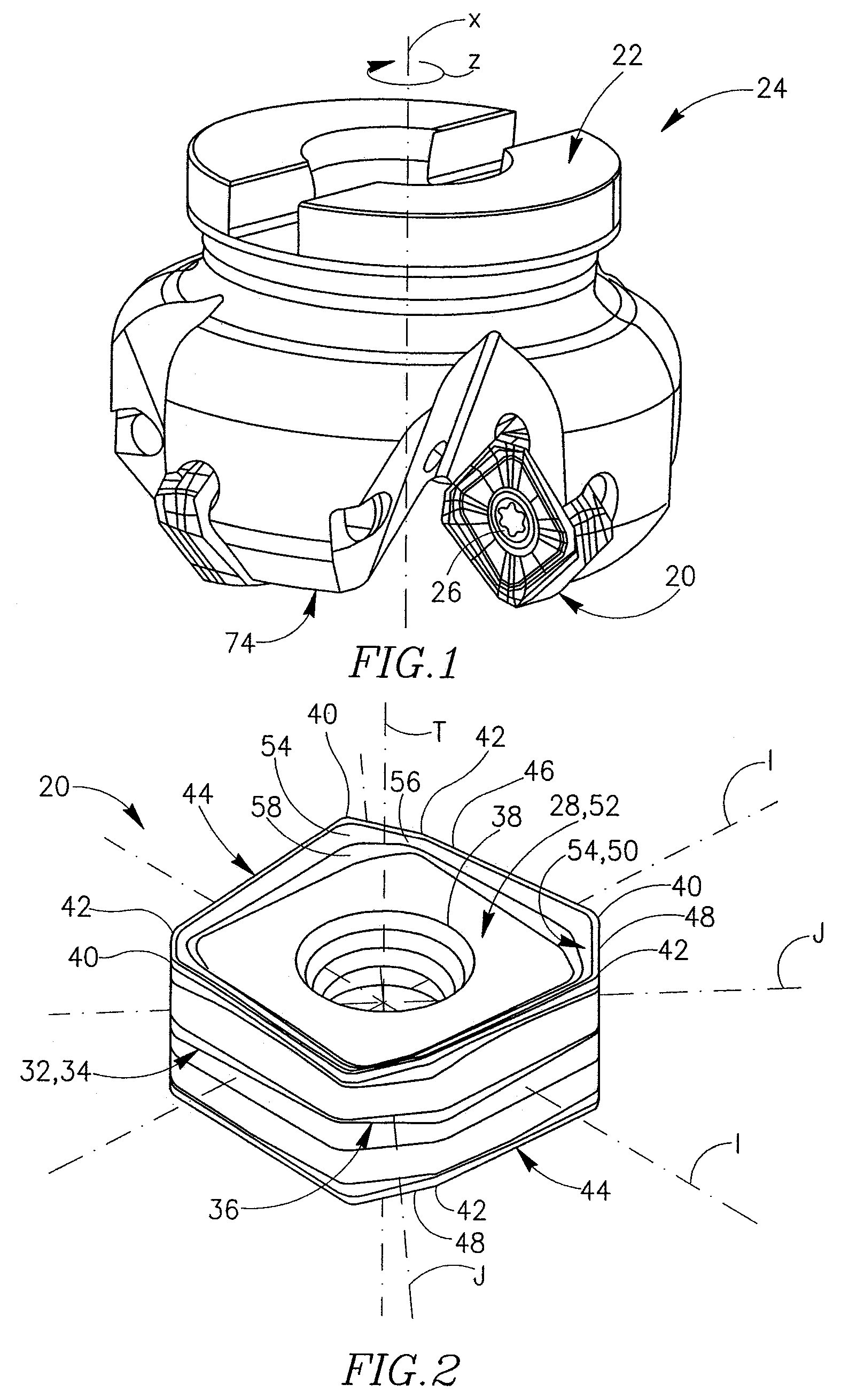
[0043]Attention is first drawn to FIG. 1. A cutting insert 20 in accordance with the present invention is secured to a cutter body 22 of a rotary milling cutter 24 by a clamping screw 26. The cutting insert 20 is of a double-sided, indexable and reversible type, and is generally adapted to perform face and 45° shoulder-milling a work-piece (not shown).

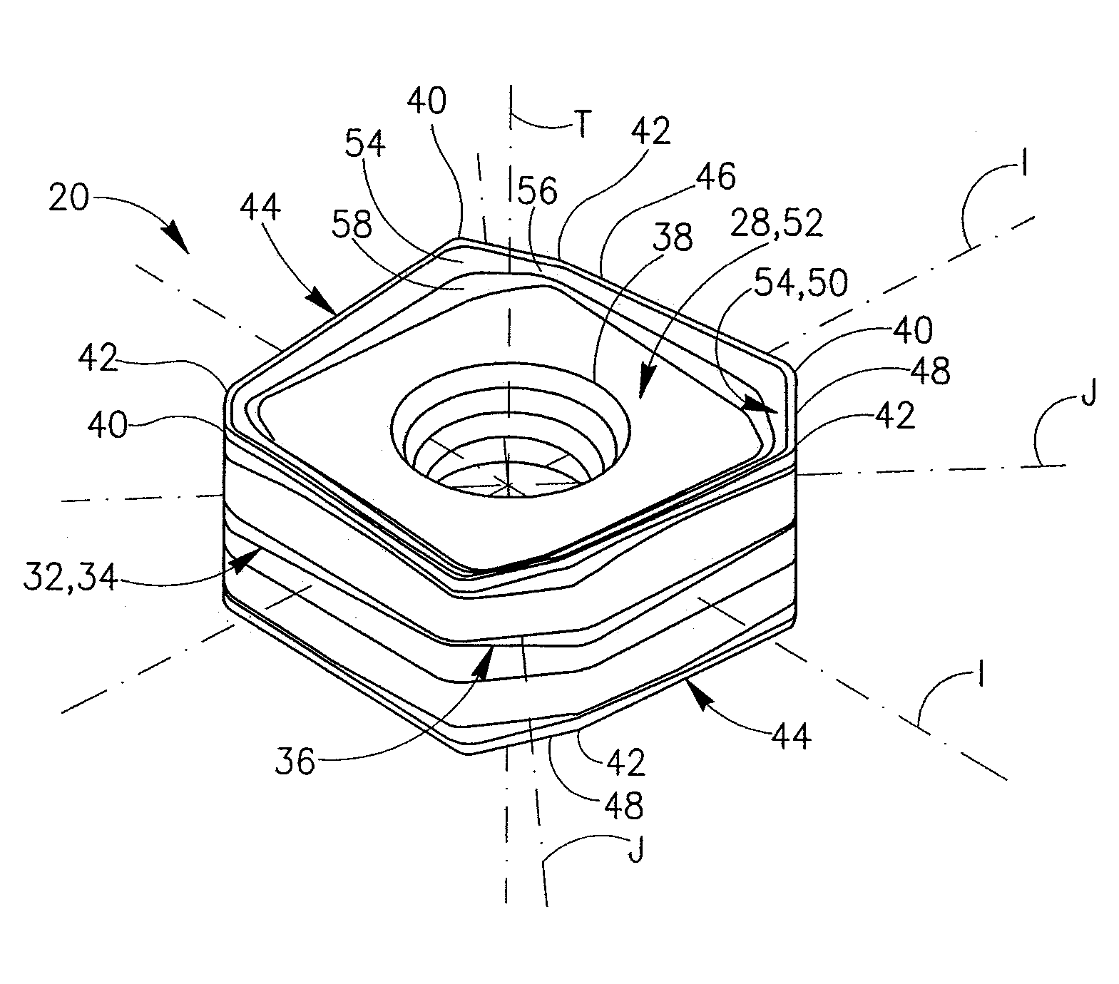
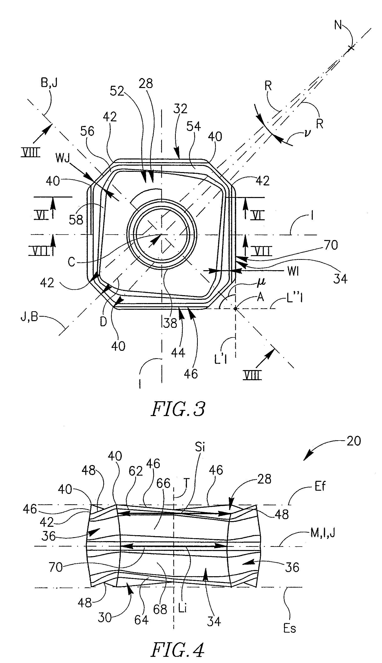
[0044]Attention is now drawn to FIGS. 2 to 5. The cutting insert 20 has identical and opposing first and second end faces 28, 30. In an end view of the cutting insert 20, best shown in FIG. 3, each of the identical first and second end faces 28, 30 is of a general form of a square having curved corners. A peripheral side surface 32 extends between the opposing first and second end faces 28, 30. The cutting insert is of a negative type and therefore the peripheral side surface 32 is generally perpendicular to both end faces 28, 30. The peripheral side surface 32 has four identical major side surfaces 34 of a generally parallelogrammatic...


PUM

PropertyMeasurementUnit
central angleaaaaaaaaaa
inner angleaaaaaaaaaa

Abstract

A double-sided reversible and indexable cutting insert has identical opposing first and second end faces and a peripheral side surface extending therebetween. A clamping through-bore extends between, and opens out to, the first and second end faces. The cutting insert has a median plane between the first and second end faces, and a through-bore axis extending perpendicularly through the median plane. The cutting insert also has a Y-fold rotational symmetry about the through-bore axis. The peripheral side surface has Y major side surfaces and Y minor side surfaces, each minor side surface interconnecting two adjacent major side surfaces. Each minor side surface is a section of a single cylindrical surface having a given radius, the given radius being greater than a minor side surface distance of each minor side surface from the through-bore axis.

Description

FIELD OF THE INVENTION[0001]The present invention relates to a double-sided, indexable and reversible cutting insert for metal cutting operations, in general, and for 45° shoulder face-milling operations, in particular.BACKGROUND OF THE INVENTION[0002]Such cutting inserts are generally provided with curved corners. U.S. Pat. No. 6,196,771 discloses a cutting insert having first and second side faces. Each side face includes a pair of minor cutting edges at each corner of the insert. The two minor cutting edges are located on two opposing sides of a corner bisector B, together forming an obtuse inner angle of about 170°, and are mirror-imaged about the bisector B. Two major cutting edges intersect respective ones of the minor cutting edges whereby each major cutting edge and its associated minor cutting edge together form a cooperating pair of cutting edges. There are two such cooperating pairs at each corner of each side face, whereby the insert has at least sixteen cooperating pair...

Claims


Application Information

Patent Timeline
Patent Type & Authority Patents(United States)
IPC IPC(8): B23B27/16
CPCB23C5/2221B23C2200/123B23C2200/201B23C2200/208Y10T407/192B23C2210/168Y10T407/24Y10T407/23B23C2210/163B23B2200/3681B23C2200/0455B23C5/2213
Inventor SMILOVICI, CAROLBALLAS, ASSAF
Owner ISCAR LTD
Why Eureka
Try Eureka